Online help for Lizzox Pure Flood
General product information
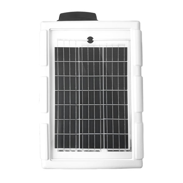
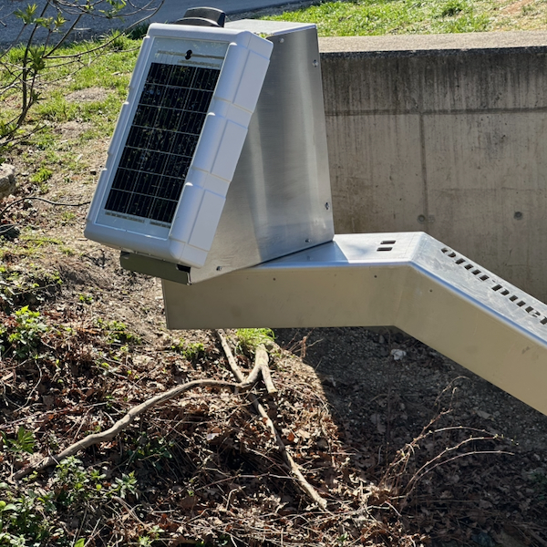
Lizzox Pure Flood has been designed to detect and monitor critical flood situations at an early stage. The focus is on the reliable detection of changes in water levels as a basis for rapid decision-making and effective early warning. It is used to record, process and transmit water levels at bridges and similarly exposed locations. By combining a PV module with a rechargeable buffer battery, the Lizzox Pure Flood can be operated as a stand-alone system. 2 level sensors can be connected and simultaneously operated. A defined threshold value determines which of the two measurement values is used as the main water level. This allows the advantages of both measurement methods to be combined when using a hydrostatic sensor and a radar sensor together, thereby achieving optimal coverage of the water level range to be monitored. When using hydrostatic level sensors with absolute pressure measurement, an additional sensor for measuring atmospheric pressure can also be connected to the Lizzox Pure Flood . 2 analogue inputs as well as one Modbus client interface (RS485) for connecting sensors. The sensors are powered directly by the Lizzox Pure Flood . The voltage output is adjustable within the range of 5...24 V . To save energy, it is only activated shortly before and during measurement. By using the mobile network to transfer data to the server, the site rarely has to be physically accessed and the data can be accessed at all times.
Product characteristics:
- Autonomous operation without external power supply
- Integrated PV module and integrated rechargeable battery
- Robust, vandal-proof device
- Redundant measurement using two level sensors (optional)
- Selection of the main level based on a threshold value Threshold-based selection of the main level with redundant measurement (optional)
- Analogue inputs for level sensors
- Modbus interface to connect level sensors
- Switchable and adjustable sensor supply
- Configurable via web interface
- Device time synchronised with server
- Very low commissioning & operating costs
- Integrated, durable SIM chip
Application:
- Early flood warning based on water level data
- Water level monitoring at critical locations
- Real-time data for operational and decision-making processes
- Event monitoring during heavy rain and flooding
- Alerts when critical thresholds are reached
This online help is applicable from:
Frequently asked questions (FAQs)
Activate the measurement system via the title bar of the configuration section "Measurement system" (see Measurement system). Then trigger a connection using the solenoid switch (see Solenoid switch) to transfer the altered configuration from the server to the device.
Hold the MDN Magnet (206.803) on the position shown in the following figure for at least 3 sec.
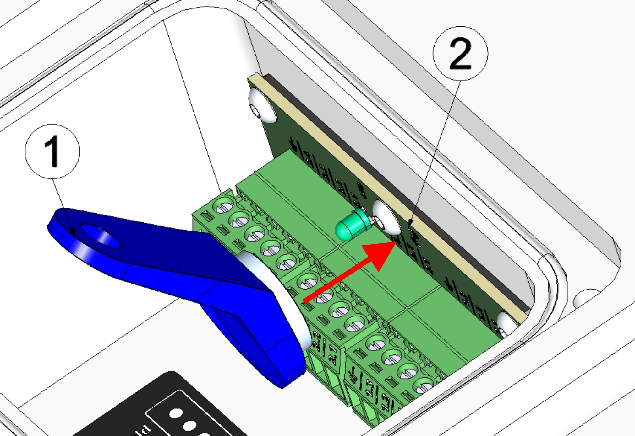
| 1 | MDN Magnet (206.803) | 2 | Lizzox Pure Flood |
Use a shielded twisted pair cable to prevent electromagnetic interference caused by the environment. The total length of the cables connecting the Modbus servers must not exceed 30 m. It is advisable to use a multi-core cable in which data and power lines can be routed together. When connecting multiple Modbus servers, only a bus structure is permitted. Stubs or star and tree topologies are not permitted.
A detailed explanation is provided in section Connecting the sensors.
Via the dropdown list "Termination", located in the "Interfaces" Tab of the input window "Device settings", the 120 Ω termination resistance between RS485 A and B can be switched on. (see Device settings , tab "Interfaces")
The RS485 interface has no clamp resistances (pull up to RS485 A and pull down to RS485 B).
A detailed explanation is provided in section Technical details about the RS485 interface.
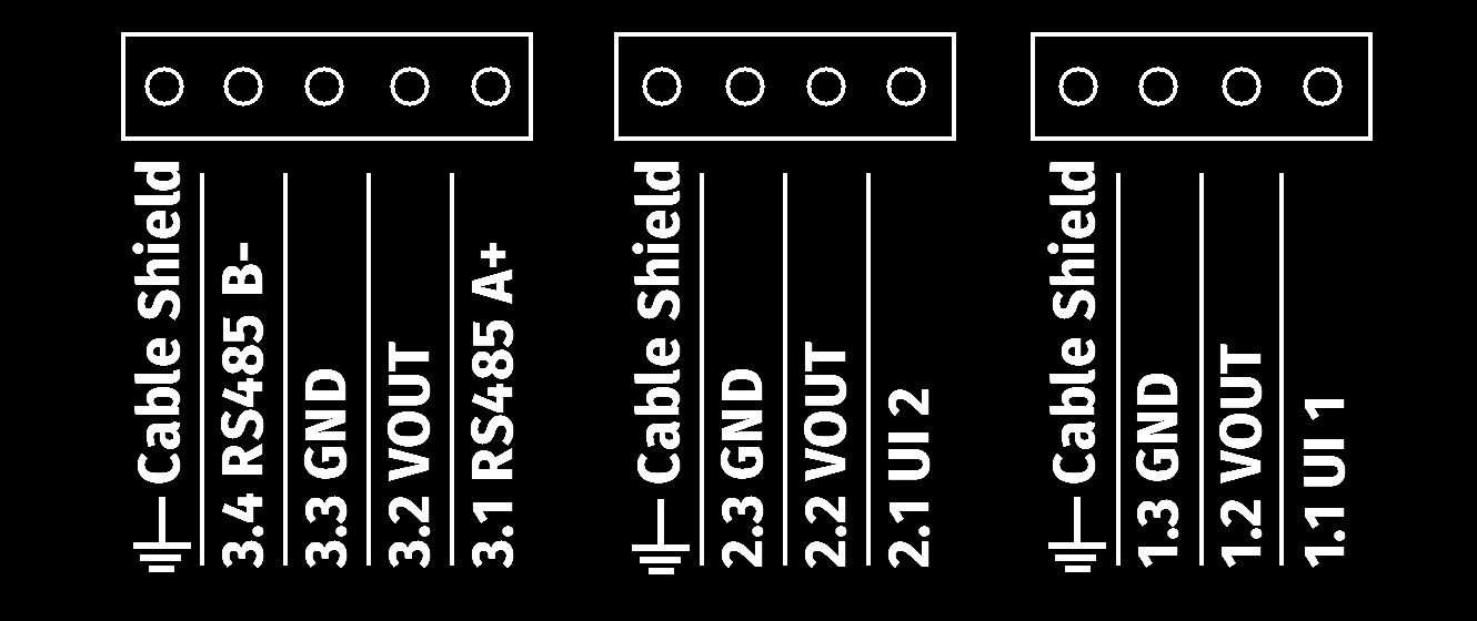
Diagram of the terminal strip

|
Cable Shield | Shielding of the sensor cable |
| 3.4 | RS485 B- | RS485 B (inverting) |
| 3.3 | GND | Ground |
| 3.2 | VOUT | Switchable and adjustable sensor supply (5...24 V ) |
| 3.1 | RS485 A+ | RS485 A (non-inverting) |
| Cable Shield | Shielding of the sensor cable | |
| 2.3 | GND | Ground |
| 2.2 | VOUT | Switchable and adjustable sensor supply (5...24 V ) |
| 2.1 | UI 2 | Universal input 2 |
| Cable Shield | Shielding of the sensor cable | |
| 1.3 | GND | Ground |
| 1.2 | VOUT | Switchable and adjustable sensor supply (5...24 V ) |
| 1.1 | UI 1 | Universal input 1 |
A detailed explanation is provided in section Connecting the sensors.
Microtronics Engineering GmbH is constantly testing various sensors with mA output or Modbus server interface (RS485) for compatibility with the Lizzox Pure Flood .
A list of compatible sensors is provided in section Compatible sensors.
Level measurement using a single radar sensor:
- Activate the Modbus Interface (see Device settings , tab "Interfaces").
- Activate the sensor supply (see Device settings , tab "Sensor supply").
- Configure the measurement channel to be used for recording the sensor value (see Sensor settings or Universal channel)
- Configure the sub level you wish to use (see Sub Level settings).
- Make sure that the other sub level is deactivated.
- Configure the main level (see Main Level settings).
A detailed explanation is provided in section Level measurement using a single radar sensor.
Combining pressure and radar sensor:
- Activate the Modbus interface (see Device settings , tab "Interfaces").
- Activate the sensor supply (see Device settings , tab "Sensor supply").
- Configure the measurement channel to be used for recording the measurement value of the radar sensor (see Sensor settings or Universal channel)
- Configure the measurement channel to be used for recording the measurement value of the pressure probe
- Configure the measurement channel to be used for recording the measurement value of the sensor for the atmospheric pressure
- Configure the sub level that you wish to use as "Level - Distance" (see Sub Level settings).
- Configure the sub level that you wish to use as "Level - Pressure".
- Configure the main level (see Main Level settings).
A detailed explanation is provided in section Combining pressure and radar sensor.
Deactivate the measurement system via the title bar of the configuration section "Measurement system" (see Measurement system). Trigger a transmission using the solenoid switch (see Solenoid switch) or use the "OnSite Companion" smartphone app to transmit the altered configuration from the server to the device (see Synchronisation with the myDatanet server).
A detailed explanation is provided in section Storage of the product.
The measurement data is assigned to the site and not to the linked device. If a device is replaced, all data (measurement values and configurations) are retained. The site is only assigned a different device by changing the serial number. From this moment on, the site receives the measurement data from the newly assigned device.
Proceed as follows to assign another Lizzox Pure Flood to the site:
- Activate standby mode on the new device (see Storage of the product). Standby mode is already active on newly delivered Lizzox Pure Flood .
- Open the default input screen for configuring the site (click on the pencil symbol in the list of sites, see "Sites / Applications" area at customer level).
- Enter the serial number of the new device in the "Device S/N" field of the configuration section "Site".
- Trigger a connection on the device to be replaced (see Solenoid switch) or trigger a synchronisation (see Synchronisation with the myDatanet server). All data that has not yet been transmitted is transferred to the server.
- Check whether all relevant data has been transferred. If necessary, trigger the connection again.
- Trigger a connection on the new device to transfer the the configuration of the site (and therefore also the assignment to the site) to the new device.
From this point on, the site receives the measurement data from the newly assigned device.
| As the replaced device is now not assigned to a site, it no longer records any data. However, it will continue to establish a connection to the server at the last set transmission interval in order to be informed about the assignment to a site if necessary. However, it is recommended to activate transport mode. To do so though, the device must be assigned to a site. The site can be deleted again after activating transport mode. |


