Device settings
Basic settings
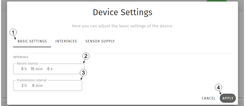
Input window "Device settings", tab "Basic settings"
| 1 | Buttons for switching between the individual tabs of the input window |
| 2 | Time between measurement data recordings |
| 3 | Time between transmissions |
| 4 | Button to apply the
settings
Note: To save the settings,
the "Save" button below the "Smart Actions" configuration section must also be
clicked.
|
Interfaces
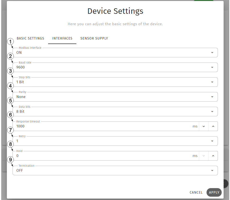
Input window "Device settings", tab "Interfaces"
| 1 | Selection whether the Modbus interface should be active | |
| Off | Interface deactivated | |
| On | Interface activated | |
| 2 | Selection of the required baud rate | |
| 3 | Selection of the required stop bits | |
| 4 | Selection of the required parity | |
| 5 | Number of data bits to be used | |
| 6 | Time during which the modbus server must react to the command from the device | |
| 7 | Selection if the commands should be repeated when a communication error occurs | |
| Off | A communication error is highlighted immediately. | |
| 1-3 | When a communication error occurs, the relevant command is repeated x times. The error is only highlighted when the selected number of attempts has failed. | |
| 8 |
Number of measurement cycles for which the measurement value is held until the error value is issued |
|
| 9 | Selection whether the 120 Ω terminating resistor betw. RS485 A and B should be active | |
| Off | Terminating resistor deactivated | |
| On | Terminating resistor activated | |
Example to explain the correlation between "Response timeout", "Retry" and "Record interval"
| Basic settings |

|
Record interval | 1 min. |
| Interfaces |
 1. attempt 1. attempt |
Response timeout | 4 sec. |
 Retry Retry |
|||
| Retry | 1 |
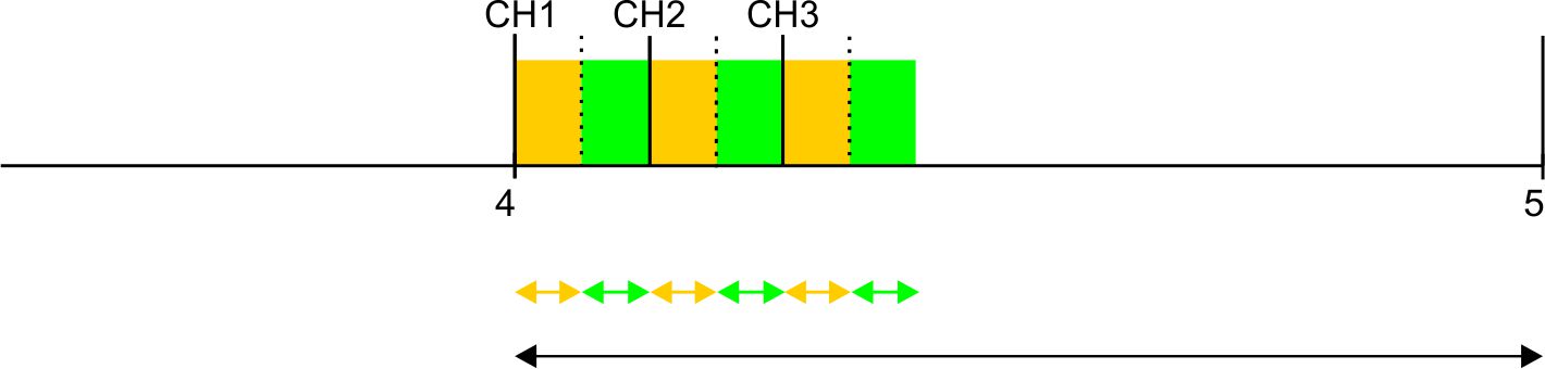
Explanation: 3 channels are activated in this example. However, the Modbus server does not respond. At the time of recording, the system first attempts to read the data for Modbus measurement channel 1. As "Retry" is enabled, once the "Response timeout" has expired, another attempt is made to read the data for Modbus measurement channel 1 from the Modbus server. Once the "Response timeout" has expired again, the error value "OL" (Open Loop) is set for Modbus measurement channel 1 and the first attempt to read the data for Modbus measurement channel 2 is initiated.
Therefore, the number of active Modbus measurement channels, the "Response timeout", the number of "Retries" and the record interval must be set as follows:
Retry not active: "Response timeout" * Number of active channels < "Record interval"
Retry active: "Response timeout" * (1+ number of retries) * Number of active channels < "Record interval"
Sensor supply
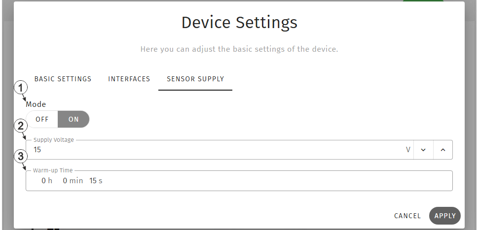
Input window "Device settings", tab "Sensor supply"
| 1 | Selection whether the sensor supply should be active | |
| Off | Sensor supply deactivated | |
| On | Sensor supply activated | |
| 2 | Selection of the output voltage for the sensor supply | |
| 3 | Time for which the sensor supply is switched on prior to measurement | |


