Measurement system
This configuration section is used to configure the basic settings of the device as well as the settings for the 2 universal inputs and the 3 Modbus measurement channels. The operating mode can also be selected in this configuration section.
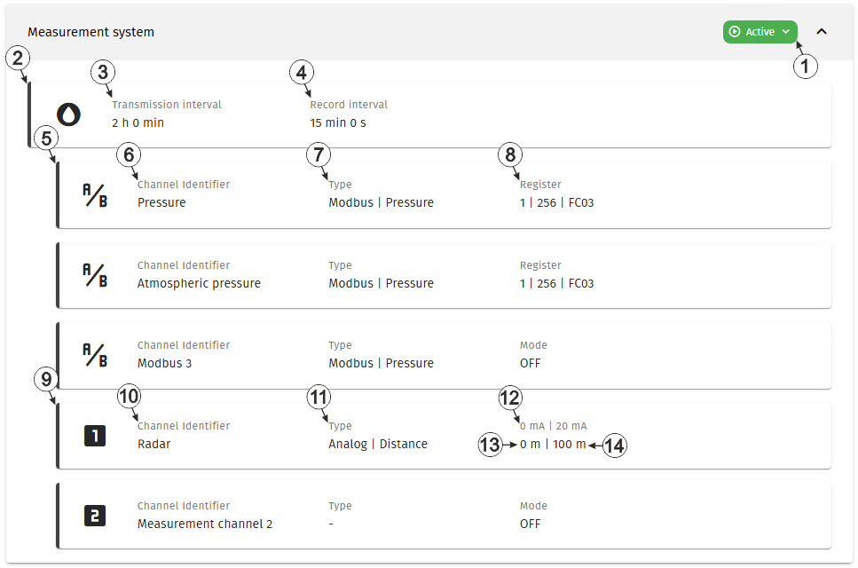
Configuration section "Measurement system"
| 1 | Current operating mode of the measurement system | |
| Activation waiting for device | The measurement system has been set to active but no device is linked to the site | |
| Activation on device required | The measurement system hs been set to active and is waiting for the device to establish a connection to the server. To proceed, please trigger a connection establishment using the solenoid switch on the Lizzox Pure Flood (see Solenoid switch). | |
| Active | Operation in accordance with the configuration | |
| Deactivation pending | The measurement system has been deactivated and is waiting for the device to confim deactivation | |
| Deactivated | The measurement system has been deactivated. All operations (measurement, recording, transmission, etc.) are suspended in order to minimise energy consumption during transport or storage. The local radio interface used by the Lizzox Pure Flood to communicate with the "OnSite Companion" smartphone app is also deactivated. | |
| Deactivation in process | The measurement system has been deactivated. An active device has then been assigned to the site. The measurement system is now awaiting confirmation of the activation from the newly assigned device. | |
| 2 | Status information about
the Lizzox Pure Flood
currently linked to the site. By clicking on this area, the input window for the basic settings of the device is opened (see Device settings ). |
|
| 3 | Time between transmissions | |
| 4 | Time between measurement data recordings | |
| 5 | Status information about a
Modbus measurement channel of the Lizzox Pure Flood
By clicking on this area, the input window for the configuration of the Modbus measurement channel is opened (see Sensor settings). |
|
| 6 | Name of the measurement value determined using the Modbus measurement channel | |
| 7 | Type of measurement channel and type of connected sensor | |
| 8 | Basic settings for the measurement channel. | |
| Mode | Measurement channel deactivated | |
| Register | Current configuration used to read the measurement
value from the sensor (server address | register address | function code) |
|
| 9 | Status information about a
universal input of the Lizzox Pure Flood
By clicking on this area, the input window for the configuration of the universal input is opened (see Universal channel). |
|
| 10 | Variable part of the name
for the measurement values determined using the universal input Two measurement values are recorded using the universal input. Their name is made up of the variable part and a fixed part ("myName - measurement value" and "myName - raw value"). |
|
| 11 | Type of measurement channel and type of connected sensor | |
| 12 | Basic settings for the measurement channel. | |
| Mode | Measurement channel deactivated | |
| 0 mA | 20 mA | Valid input signal range 0...20 mA (0 mA = 0 %, 20 mA = 100 %) | |
| 4 mA | 20 mA | Valid input signal range 4...20 mA (4 mA = 0 %, 20 mA = 100 %) | |
| 13 | Start of the measurement range in the measurement unit or "Off" if the measurement channel is deactivated | |
| 14 | End of the measurement range in the measurement unit or "Off" if the measurement channel is deactivated | |


