Determining the measurement values
The module chain described in the following is started in the configurable record interval and executed once. The interval can be adjusted via the parameter "Record interval" (see Device settings ).
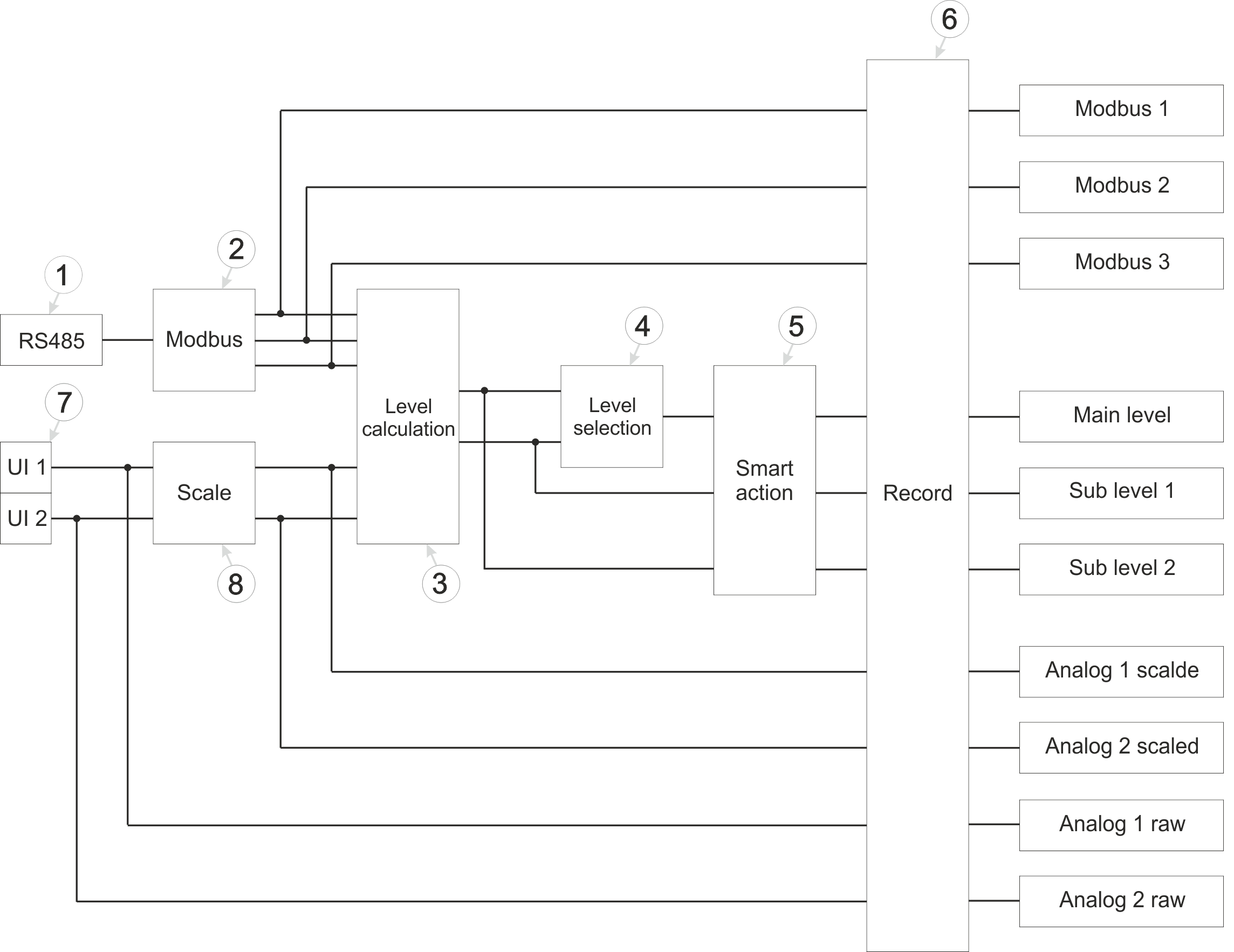
Schematic diagram of how measurement valuesare generated
| 1 | Determining data via the RS485 interface that is provided by sensors with Modbus interface (see RS485 module) | 5 | Monitoring of the conditions under which a "Smart Action" is triggered (see Smart Action module) |
| 2 | Generating measurement values based on the data received via the RS485 interface (see Modbus module) | 6 | Carrying out recording (see Record module) |
| 3 | Calculation of the two sub levels (see Level calculation module) | 7 | Determining the raw values of a sensor with mA output (see UI module) |
| 4 | Determining which of the two sub levels is recorded as main level (see Level selection module) | 8 | Rescaling from raw value to measurement value (see Scale module) |
RS485 module
This module handles communication with sensors featuring a Modbus interface. The module acts as a Modbus client. All parameters on the "Interfaces" and "Sensor Supply" tabs of the input window "Device Settings" are relevant for this module (see Device settings ).
Modbus module
This module generates the measurement values for the 3 Modbus measurement channels. In this process, two registers of the sensor are read from the configured Modbus address and interpreted as a 32-bit floating-point number with "HI-LO" word order. It is therefore assumed that the HI word is stored in the lower register address (i.e. the address specified in the configuration) and the LO word in the higher register address. The read value is accepted unchanged. The buttons for selecting the sensor type (distance or pressure) can only be used to specify whether the read value should be interpreted as a distance value in metres or as a pressure value in bar. Scaling or conversion is not possible.
For this module, all parameters of the input window "Sensor settings" are relevant (see Sensor settings).
Level calculation module
This module calculates the two sub levels taking mounting height into account. The starting point is Dieses Modul berechnet die beiden Einzelpegel unter Berücksichtigung der Montagehöhe.The starting point in each case is at least one of the measurement values generated by the Modbus or Scale module. The method of calculation depends on the selected mode.
If the mode "Distance" has been selected, the measurement value to be used must be specified via the "Sensor list" drop-down list in the "Sub level settings" input window. In this case, the individual level is calculated by subtracting the measurement value from the mounting height.
If the mode "Absolut pressure compensated" has been selected, two measurement values are required to calculate the sub level, which are the pressure in the medium (i.e. in the water) and the atmospheric pressure as a reference value. These values can be selected via the dropdown lists "Medium pressure" and "Air pressure" in the input window "Sub level settings". Die Berechnung des The individual level is calculated in several stages. First, the difference between the pressure in the medium and atmospheric pressure is determined. To convert the pressure value into the height of the water column, this difference is multiplied by 10.1936799 (conversion factor for fresh water)10,1936799. If the height of the water column calculated in this way exceeds the configured "Minimum infiltration height", the mounting height is added in a final step to obtain the sub level.
For this module, all parameters of the input window "Sub level settings" are relevant (see Sub Level settings).
Level selection module
This module determines which of the two sub levels is used as main level and recorded.
The primary sub level is selected via the dropdown liste "Primary sub level" in the input window "Main level settings". The second sub level is automatically used as secondary sub level. As long as the measurement value of the primary sub level is below the threshold value determined via the input field "Threshold of primary sub level", the secondary sub level is used and recorded as main level. If the threshold value is exceeded, the primary sub level is used and recorded as main level.
Regardless of the threshold value, if the sensor used for the active sub level fails, the system automatically switches to the other sub level. As both sub levels are continuously monitored in parallel, there is no interruption to the recorded main level measurement data.
For this module, all parameters of the input window "Main level settings" are relevant (see Main Level settings).
Smart Action module
This module is used to monitor the conditions under which a "Smart Action" is triggered. However, the Smart Action module is only available for the main level, the two sub levels, the inpt voltage and the State of charge.
For this module, all parameters of the input window "Smart Actions" are relevant (see Smart Actions).
Record module
The measurement values are recorded using the record module.
The following table specifies the relevant parameters for the module:
| Configuration section | Parameter | Erklärung |
|---|---|---|
| Measurement system -> Device settings | Record interval | Time between measurement data recordings |
Scale module
This module rescales the raw value (e.g. mA) to the required measurement value (e.g. m or bar). Whether the measurement value is to be a distance value in meters or a pressure value in bar is determined via the selection of the sensor type.
For this module, all parameters of the input window "Universal input" are relevant (see Universal channel)


