Technical details regarding the sensor supply VOUT
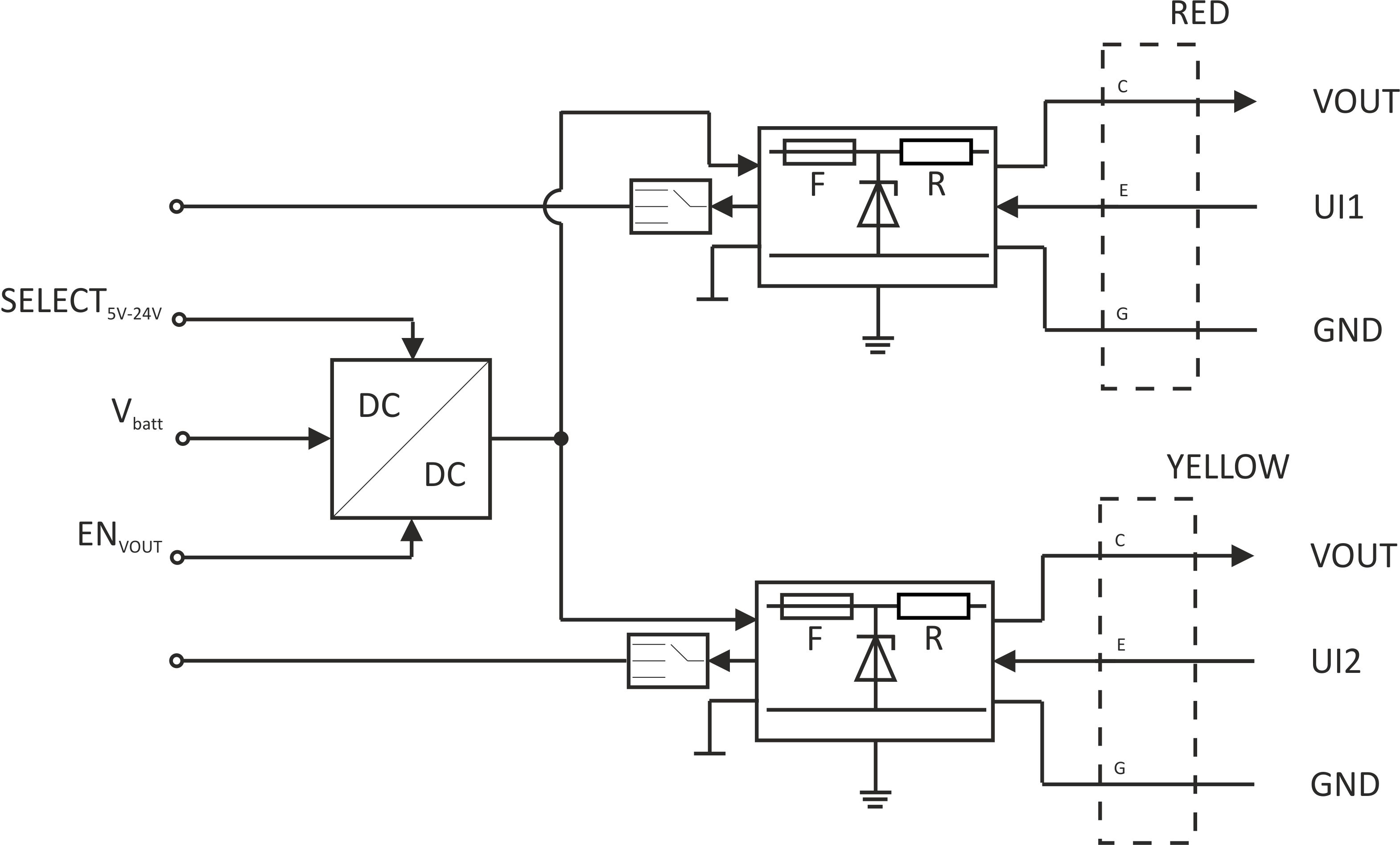
Schematic diagram of the sensor supply
| Vbatt | Internal supply voltage |
| SELECT5V-24V | Selection of the output voltage for the sensor supply. This can be done via the parameter "voltage", which is located in the input mask for configuring the output channels (see Output channels). |
| ENVOUT | The sesor supply is activated briefly before and during the measurement. The selection of how long before the measurement the sensor supply is activated can be made via the parameter "Ext. warmup time", which is located in the input mask for configuring the output channels (see Output channels) |
| F | Zener barrier fuses (see Zener barrier) |
| R | Zener barrier resistance (see Zener barrier) |
| VOUT | Sensor supply VOUT (5...24 V ) |
| UIx | Universal input |
| GND | Ground |
Each measurement channel has its own Zener barrier. The output voltage of the internal DC/DC converter is conducted via both of the Zener barriers and is then connected to the "VOUT" of the connector of the relevant measurement channel. The parameter "voltage" located in the input mask for configuring the output channels (see Output channels) allows for varying the output voltage of the DC/DC transformer between 5...24 V For each signal path ("VOUT" and "UIx"), every Zener barrier has one internal fuse that cannot be replaced (Ifuse int.) and one fuse that can be replaced by the user (Ifuse ext.). The specifications for these fuses are detailed in the chapter Zener barrier. Instructions on replacing the fuse are provided in chapter Fuse replacement.
- The sensor supply VOUT must always be less than Uo of both Zener barriers.
- The minimum value for the sensor supply VOUT is calculated as follows:
VOUTmin = VSensor min. + 1.5 V + (22 mA * (50 Ω + R))
VSensor min.:
R:
Min. permissible supply voltage for the sensor
Zener barrier resistance (see Zener barrier)
- The values for Uo of both Zener barriers should not differ greatly as the sensor supply VOUT cannot be set separately for both measurement channels. It must always be ensured that the sensor supply VOUT can be set high enough so that both sensors receive an adequate supply while ensuring it is not greater than Uo of one of the two Zener barriers.
Ex parameter
The Ex parameters Uo, Io, Po, Lo and Co that are valid for the relevant measurement channel ("red" or "yellow") are detailed on the type plate of the myDatalogEASY IoT ATEX (see Device labelling) and are based on the Zener barrier selected when placing the order. An overview of available Zener barriers and their relevant Ex parameters are detailed in chapter Zener barrier.


