Measurement system
This configuration section is used to configure the basic settings of the device as well as the settings for the up to 4 remote sensor modules.
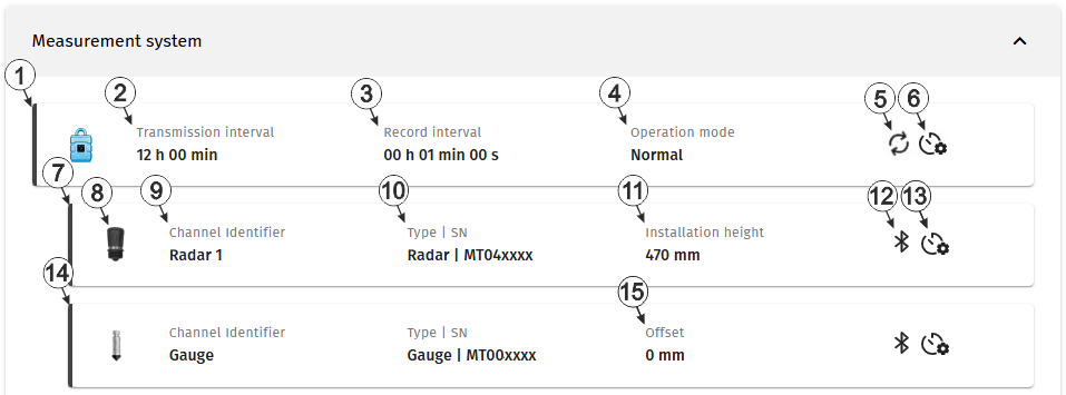
Configuration section "Measurement system"
| 1 | Status information about the
site linked to Jellox Node . The input window for the basic settings of the device is opened by clicking on this section (see Device settings ). |
|
| 2 | Time between transmissions | |
| 3 | Time between measurement data recordings | |
| 4 | Current operaing mode of the device | |
| normal | Operation in accordance with the configuration | |
| transport | Transport lock activated. This means that all of the operations (measurement, recording, transmission, etc.) are stopped to minimise energy consumption during transport or storage. | |
| 5 | This symbol is shown if the device is currently connected to the server and is transmitting data. | |
| 6 | When you move the mouse pointer over this symbol, the time remaining until the next battery replacement of the device is displayed as a tooltip. | |
| 7 | Status information about the sensor module
currently linked to the first measurement channel
The input window for the configuration of the sensor module is opened by clicking on this section (see Remote sensor module of type Radar and Remote sensor module of type Gauge). |
|
| 8 | Icon of
the sensor module that is linked to the measurement channel
For the sensor module types "Radar" and "VEL-R-5", the colour of the colour cap used can be specified via the configuration of the sensor module. The selected colour is also displayed on the icon. |
|
| 9 | Variable part of the name
for the measurement values determined using the sensor module assigned to this
measurement channel.
Several measurement values are recorded for each of the remote measurement channels. Their name is made up of the variable part and a fixed part which depends on the type of sensor module it is assigned to (e.g. "myName - Level", "myName - Distance", etc. for sensor modules of the type "Radar"). |
|
| 10 | Type and serial number of
the sensor module.
When hovering over this section with the cursor, the version number of the firmware installed on the sensor module is displayed as tooltip. |
|
| 11 | Value for the installation height (module of the type "Radar") | |
| 12 | Status of the local radio connection between device and sensor module | |

(blinking) |
|
|
|
|
|
|

|
|
|
| 13 | When hovering over this symbol with the cursor, the remaining time until the next battery replacement of the sensor module is displayed as tooltip. | |
| 14 | Status information
about the sensor module that is currently linked to the second measurement
channel
The input window for the configuration of the sensor module is opened by clicking on this section (see Remote sensor module of type Radar and Remote sensor module of type Gauge). |
|
| 15 | Value for the offset (modul of the type "Gauge") | |
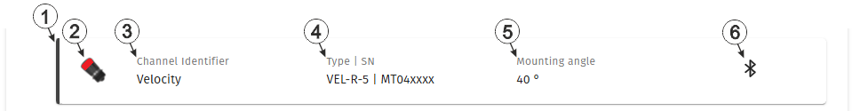
Configuration section "Measurement system, status information "VEL‑R‑5 sensor module"
| 1 | Status information about a
sensor module of type "VEL‑R‑5 " that
is linked to a measurement channel A click on this area opens the input window for configuring the sensor moudule (see Remote sensor module of type VEL-R-5). |
|
| 2 | Icon of
the sensor module that is linked to the measurement channel
For the sensor module types "Radar" and "VEL-R-5", the colour of the colour cap used can be specified via the configuration of the sensor module. The selected colour is also displayed on the icon. |
|
| 3 | Variable part of the name
for the measurement values determined using the sensor module assigned to this
measurement channel.
Several measurement values are recorded for each of the remote measurement channels. Their name is made up of the variable part and a fixed part which depends on the type of sensor module it is assigned to (e.g. "myName - Level", "myName - Distance", etc. for sensor modules of the type "Radar"). |
|
| 4 | Type and serial number of
the sensor module.
When hovering over this section with the cursor, the version number of the firmware installed on the sensor module is displayed as tooltip. |
|
| 5 | Value for the mounting angle | |
| 6 | Status of the local radio connection between device and sensor module | |
|
(blinking) |
|
|
|
|
|
|
|
|
|
|


