Strut/rod mounting
One of the mounting kits listed in the table below is required for the installation on a strut/rod. The mounting kits differ only in the length of the swivel arm included. This also determines the distance between the contact surface of the flange and the centre of the sensor recess. The mounting kits listed in the table below are suitable for struts androds with a diameter of 15-26 mm. For thicker pipes the mounting kits listed in chapter Pipe mounting can be used.
| Radar rung mounting kit | Radar rung mounting kit long | |
|---|---|---|
| Item number | 301482 | 400408 |
| Length of the swivel arm | 140 mm | 390 mm |
| Flange contact surface to centre sensor recess | 240 mm | 490 mm |
|
|
| How-To-Video: Strut/rod mounting |
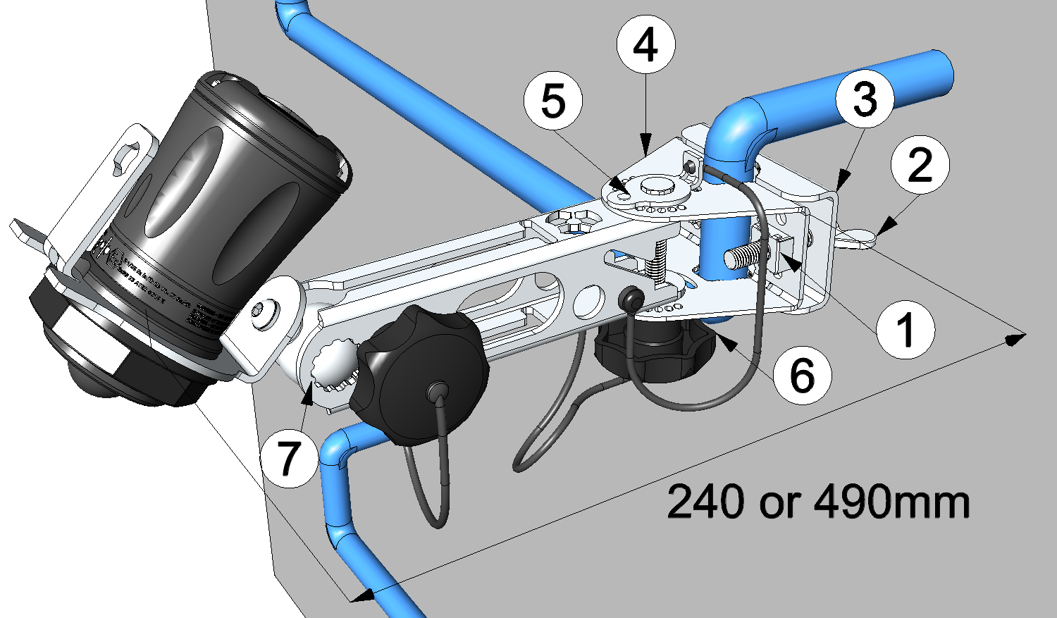
Strut/rod mounting
| 1 | Cage nut | 5 | Bolt head fitted with a lock pin |
| 2 | Wing bolt | 6 | Clamping screw |
| 3 | Clamping piece | 7 | Swivel arm |
| 4 | Flange suitable for strut/rod mounting |
- Position the flange on the strut/rod and use the clamping piece together with the wing
bolts to fasten it.
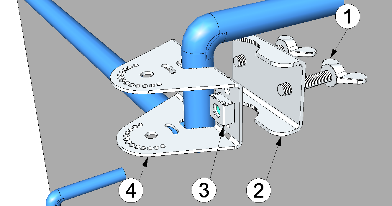
Attaching the flange on the strut/rod
1 Wing bolt 3 Cage nut 2 Clamping piece 4 Flange suitable for strut/rod mounting - Attach the swivel arm to the flange already mounted on the strut/rod using the clamping
screw (consisting of the star knob and the coach bolt fitted with a lock pin in the bolt head).
Thanks to the locking pin that is fitted on the bolt head and the holes on the front edge of the flange, the swivel arm can be locked in 15° increments at an angle of up to 90° relative to the centre axis. This applies to both left and right rotation. If a different angle is required, you can also insert the screw so that the locking pin engages in the elongated hole in the flange. In this case, however, the resistance to twisting of the swivel arm is determined only by the clamping force generated by the clamping screw.
Tip: The swivel arm is designed in such a way that the orientation of the clamping screw (star knob at the top or bottom) is irrelevant.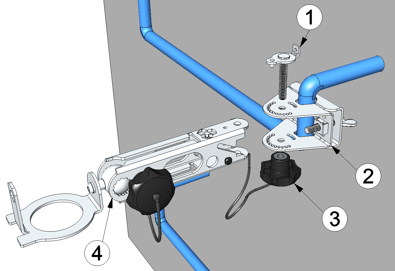
Attaching the swivel arm to the flange
1 Coach bolt fitted with a lock pin in the bolt head 3 Star knob 2 Flange suitable for strut/rod mounting 4 Swivel arm - Insert the VEL‑R‑5 in the sensor recess of the swivel arm and align it correctly. Detailed instructions on this are provided in chapter Flexibly adjustable mounts.


