Flexibly adjustable mounts
For the installation of the VEL‑R‑5 , flexibly adjustable mounts are available for various installation situations (see Assembly sets). The alignment of the VEL‑R‑5 with the flume to be measured is carried out for all flexibly adjustable mounts using the procedure described below.
Aligning the VEL‑R‑5 using the laser distance meter
| 1 | Laser meter Bosch GLM50-27CG 301757 |
| 2 | Laser meter adapter Bosch PRO GLM 50-xxx (301756, optional accessory) |
| 3 | Sensor holder |
- First, install the sensor bracket that is suitable for your installation situation. You will find further information in the chapters Wall mounting (flexibly adjustable mount), Pipe mounting and Strut/rod mounting.
- Roughly align the swivel arm of the sensor mount with the flume to be detected. If necessary, you may need to unlock the swivel arm using the corresponding clamping screw.
- Activate the angle measurement (spirit level symbol) on the laser distance meter and
insert it into the optional accessory "Laser meter adapter Bosch PRO GLM 50-xxx
" (301756). Then
position the Laser meter adapter Bosch PRO GLM 50-xxx
in the
sensor holder.
Note: The display of the laser distance meter must be positioned perpendicular to the axis along which the sensor holder is to be tilted later.The following laser distance meters are compatible with the adapter:
- Bosch PRO GLM 50-27 CG
- Bosch PRO GLM 50-27 C
- Bosch PRO GLM 50-25 G
- Bosch PRO GLM 50-23 G
- Bosch PRO GLM 50-22
- Bosch PRO GLM 40-31
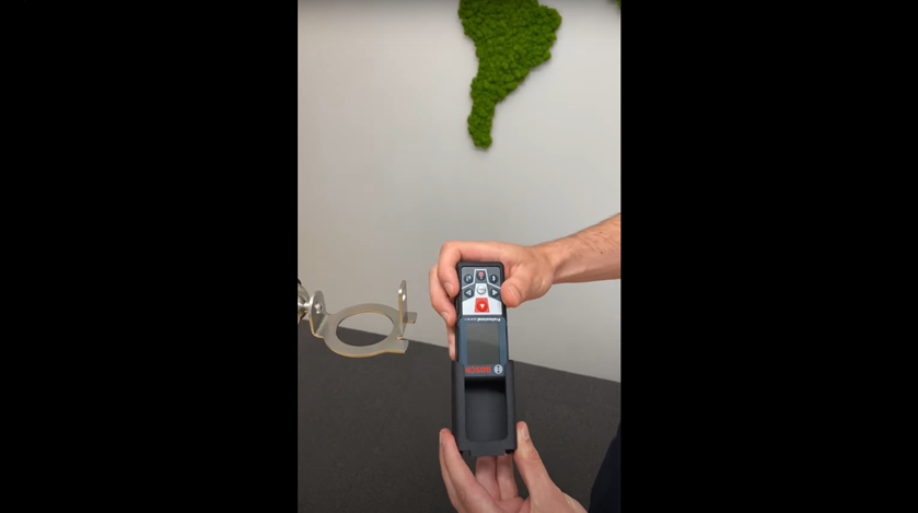
How-To-Video: Using a laser distance meter 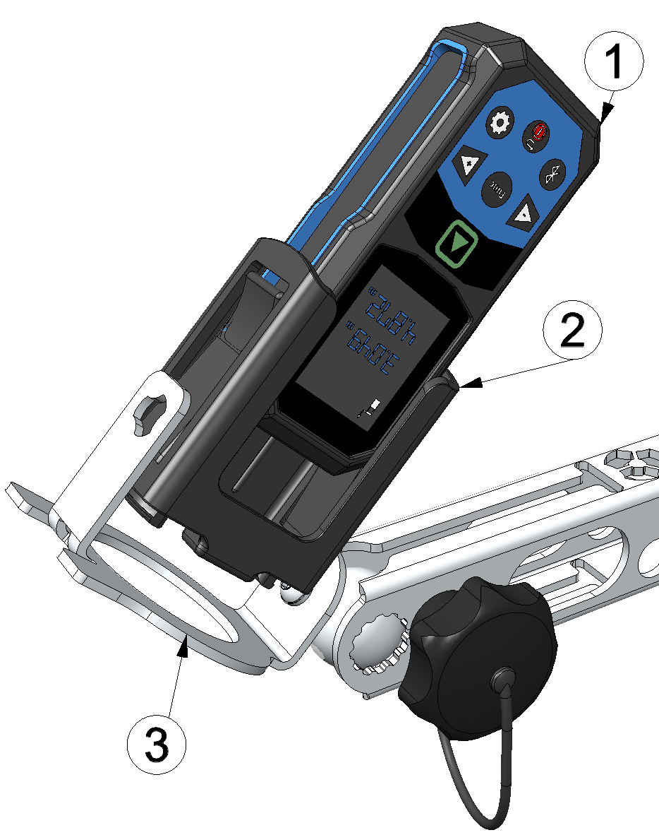
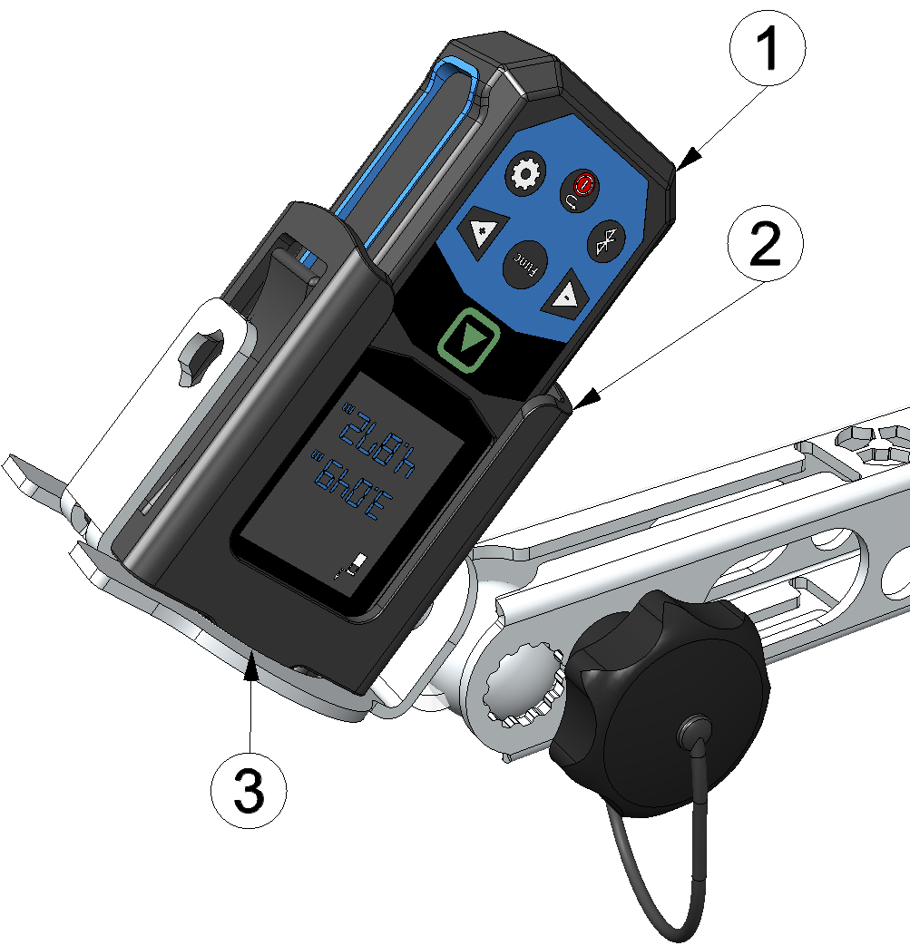
Inserting the laser distance meter into the sensor holder
1 Laser meter Bosch GLM50-27CG 301757 2 Laser meter adapter Bosch PRO GLM 50-xxx (301756) 3 Sensor holder - Loosen the clamping screw to unlock the ball joint. Then use the laser distance meter
display to adjust the sensor mount to the desired angle of attack. An angle of 45° is
recommended (see Framework conditions for a reliable measurement). Meanwhile you can also activate the distance measurement (distance
symbol) on the laser distance meter in between to use the laser beam to determine the
point at which the surface velocity is measured.
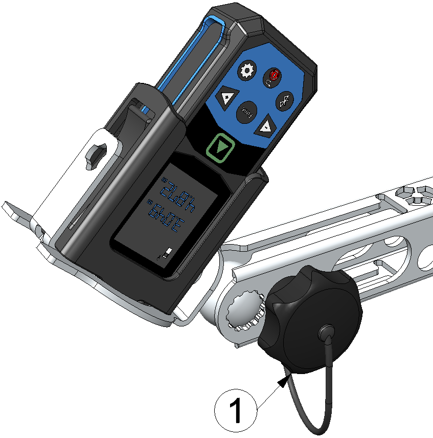
Aligning the sensor bracket
1 Clamping screw to unlock the ball joint - Fixieren Sie das Kugelgelenk durch festziehen der Spannschraube wieder und notieren Sie den eingestellten Anstellwinkel. Dieser muss später in die Eingabemaske zur Konfiguration des mit dem VEL‑R‑5 verknüpften Datenloggers eingetragen werden, damit die Oberflächengeschwindigkeit korrekt berechnet werden kann.
- Remove the Laser meter adapter Bosch PRO GLM 50-xxx
from
the sensor holder of the bracket. Then insert the VEL‑R‑5
into the sensor holder and secure it using the
G
1½" union nut supplied with the VEL‑R‑5
. The "top
marking" (horizontal line between the two arrows on the type plate) must be aligned
upwards and the longitudinal axis of the sensor, which is inclined at 45°, must be aligned
parallel to the flow.
Note: Ensure that you do not change the alignment (ball joint and swivel arm) of the sensor bracket.
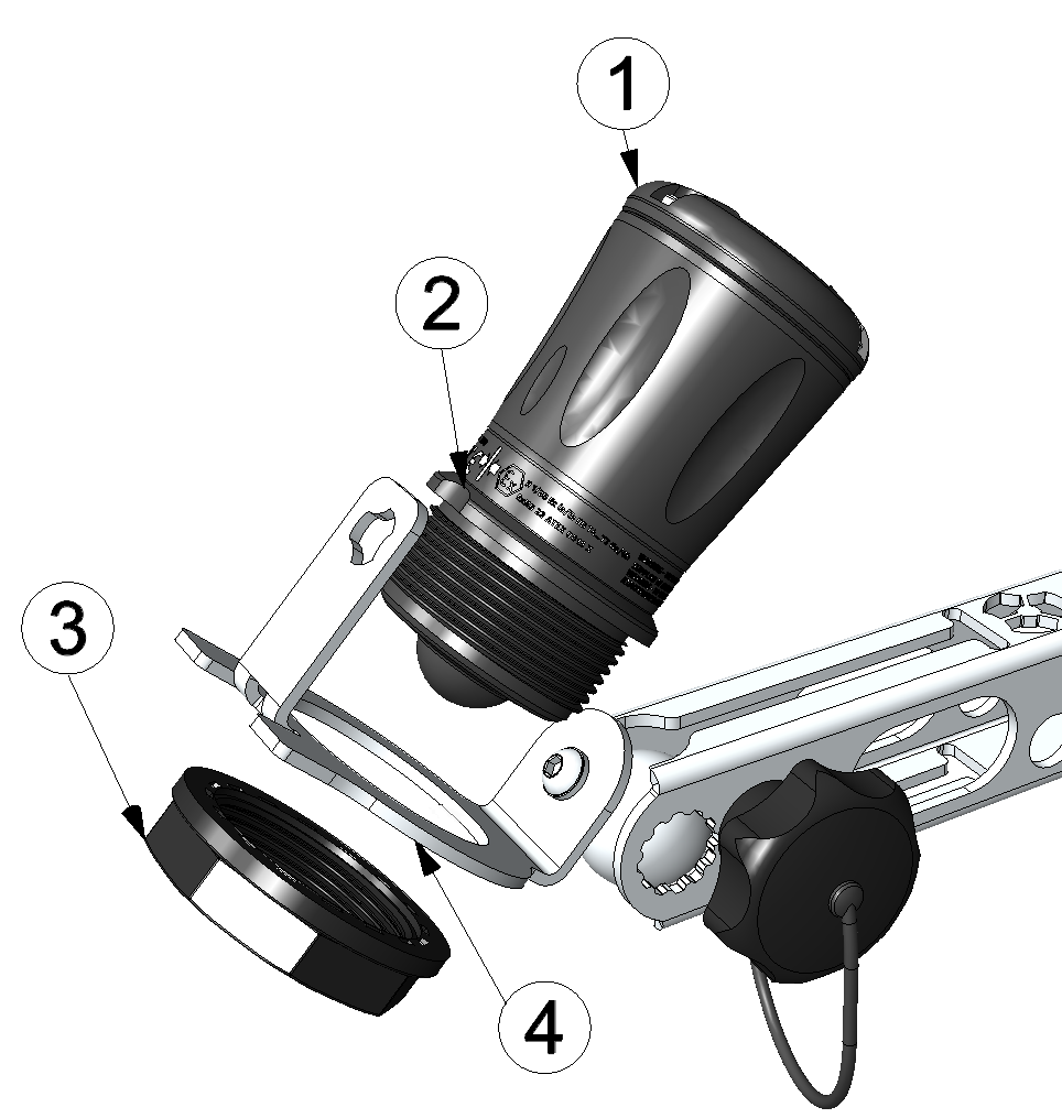
Inserting the VEL‑R‑5 into the sensor bracket
1 VEL‑R‑5 2 Top marking 3 G 1½" union nut 4 Sensor holder 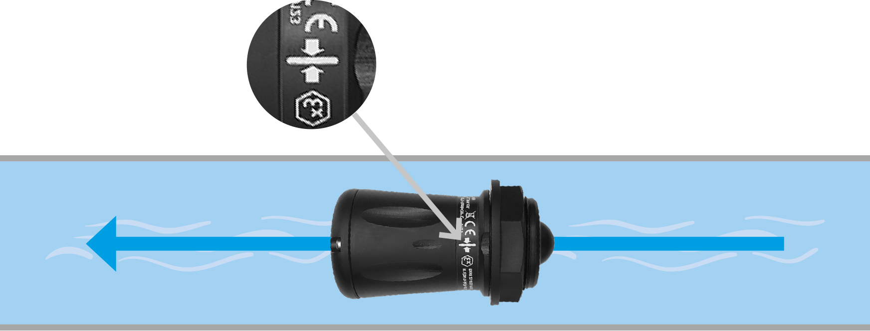
Correct alignment of the VEL‑R‑5 relative to the flow (view from above)


