Measurement system
In this configuration section, the basic settings for the device and the settings for the 4 inputs are made.
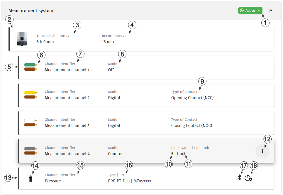
Configuration section "Measurement system"
| 1 | Current operating mode of the measurement system | |
| Activation waiting for device | The measurement system has been set to active but no device is linked to the site | |
| Activation on device required | The measurement system hs been set to active and is waiting for the device to establish a connection to the server. To proceed, please trigger a connection establishment using the reed switch on the device (see Reed switch). | |
| Active | Operation in accordance with the configuration | |
| Commissioning | Guided commissioning process has been initiated | |
| Deactivation pending | The measurement system has been deactivated and is waiting for the device to confim deactivation | |
| Deactivated | The measurement system has been deactivated. All operations (measurement, recording, transmission, etc.) are suspended in order to minimise energy consumption during transport or storage. The local radio interface used by the device to communicate with the smartphone app is also deactivated. | |
| Deactivation in process | The measurement system has been deactivated. An active device has then been assigned to the site. The measurement system is now awaiting confirmation of the activation from the newly assigned device. | |
| 2 | Information about the Jellox Pulse
currently linked to the site. The input window for the basic settings of the device is opened by clicking on this field (see Device settings). |
|
| 3 | Time between transmissions | |
| 4 | Time between measurement data recordings | |
| 5 | Information about the first
input. The input window for configuring the input is opened by clicking on this field (see Input in "Digital" mode and Inputs in "Counter" mode). |
|
| 6 | Colours of the pair of
wires for the input; the brown wire is the common ground. Tip: Only
applicable if the "Connection cable 7pin 8 m "
(301689) or the Connection cable 7pin 0,5 m "
(400442) is used. |
|
| 7 | Variable part of the Name
for the measurement values Several measurement values are recorded for each input. Their name is made up of the variable part and a fixed part that depends on the selected mode (e.g. "myName - contact position" and "myName - actuation state" for inputs in "Digital" mode). |
|
| 8 | Basic settings for the measurement channel | |
| Off | Measurement channel deactivated | |
| Digital | Digital input (Detecting the switching state of a digital contact) | |
| Counter | Infinite counter (Adding up the pulses of a water meter) | |
| 9 | Type of
contact connected to the input
Tip: The
following applies to both types:
|
|
| Opening contact | The contact is closed in idle state (i.e. current is flowing). When actuated, the contact opens. | |
| Closing contact | The contact is open in the idle state (i.e. no current flows). When actuated, the contact closes. | |
| 10 | Quantity (e.g. litres) that corresponds to a pulse of a connected meter. | |
| 11 | Unit (e.g. m³) in which the meter reading is to be displayed on the server interface. | |
| 12 | Opens the context menu for
adapting the meter reading according to the meter connected to the input (see Set meter reading). Tip: The meter reading can only be set when the device is
online. |
|
| 13 | Status information about the sensor module
currently linked to the first measurement channel
The input window for the configuration of the sensor module is opened by clicking on this section (see Remote sensor module of type PRE-PT-D30). |
|
| 14 | Icon of the sensor module that is linked to the measurement channel | |
| 15 | Variable part of the name for the
measurement values determined using the sensor module assigned to this measurement
channel.
Several measurement values are recorded for each of the remote measurement channels. Their name is made up of the variable part and a fixed part which depends on the type of sensor module it is assigned to (e.g. "myName - Meter reading", "myName - Quantity", etc. for sensor modules of the type "PRE-PT-D30"). |
|
| 16 | Type and serial number of
the sensor module.
When hovering over this section with the cursor, the version number of the firmware installed on the sensor module is displayed as tooltip. |
|
| 17 | Status of the local radio connection between device and sensor module | |

(blinking) |
|
|
|
|
|
|

|
|
|
| 18 | When hovering over this symbol with the cursor, the remaining time until the next battery replacement of the sensor module is displayed as tooltip. | |


