Online help for myDataconC3 MBM
General product information
ThemyDataconC3 MBM is a compact, stationary measurement system designed for installation in control cabinets. In addition to recording and transferring analogue or digital signals, it can be used for control and regulating tasks. The measurement system requires a continuous power supply. However, the data logger has an integrated rechargeable buffer battery which allows sending a notification in the event of a voltage supply failure. The measurement data of the inputs are determined in an adjustable interval and together with the states of the outputs they are temporarily stored in an internal data memory. This stored data is sent to a central server for further processing in a freely selectable interval using the mobile network. The measurement system is equipped with an integrated SIM chip for establishing a mobile connection. By using the mobile network to transfer data to the server, the site rarely has to be physically accessed and the data can be accessed at all times.
Product characteristics:
- Modbus client
- Modbusvia RS485 interface
- Operating mode Modbus/RTU
- Universal inputs for digital and analogue signals
- Relay outputs
- Integrated rechargeable buffer battery to issue a message in the event of a power supply failure
- Measurement value storage on the device
- Data transmission to the server via mobile network
- Location-independant management of the measurement sites via internet
- Adjustable record and transmission interval
- Device time synchronised with the sever
- Hardware real-time clock
- Very low commissioning & operating costs
- Integrated durable SIM chip
Application:
- Data exchange with Modbus server
- Data collection
- Transmission of measurement values of probes
- Asset monitoring
- Alarm monitoring
This online help is applicable from:
- Firmware version: 02v009
- IoT app version: 12v000
- Server version: 54v00x
- Product revision: 1.2 (M1/NB1 EU) / 1.7 (2G/4G World)
Frequently asked questions (FAQs)
| Blink code | Colour | Description |
|---|---|---|
| 1x | green | Last connection OK |
| 2x | red | Last transmission faulty |
| 7x | red | Network block/no matching provider |
| 8x | red | No mobile network |
| 10x | red | No mobile network connection |
| 11x | red | No server available |
| 12x | red | Faulty SIM chip |
A detailed explanation is provided in section Status LED.
When the power supply is connected, the device automatically establishes a connection. The status LED initially flashes green to indicate that a connection is being established. Once the connection has been established, the status LED remains lit green.
If the connection has been interrupted, you can initiate the connection manually by holding down the "MDN" button for at least 3 seconds. You can recognise that there is currently no connection by the fact that the status LED is either off or displaying one of the error/status codes (see Status LED).
Regardless of the connection type selected (online or interval), the myDataconC3 MBM will automatically attempt to re-establish the connection if it is lost (see Procedure in case of connection aborts).
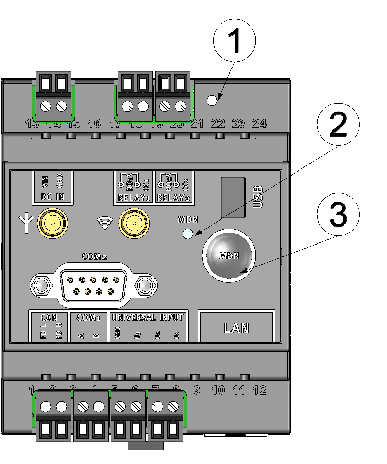
Operating elements
| 1 | Reset button | 3 | Button to trigger another connection establishment or a complete device synchronisation |
| 2 | Status LED |
The status LED is used both to display the error/status codes and to indicate the current operating state. The error/status codes are issued every 3 seconds unless there is an active mobile network connection.I.e. the output of error and status codes does not need to be enabled separately.
A detailed description is provided in section Status LED.
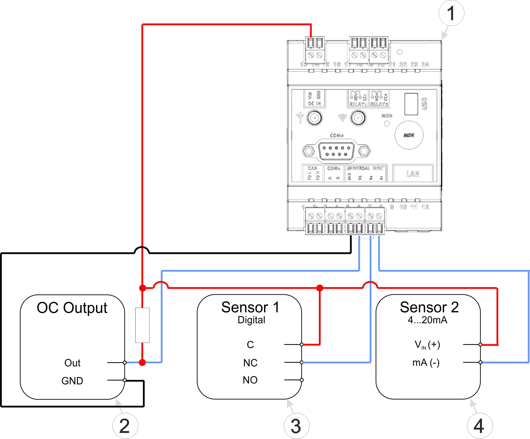
Connection examples (OC output, digital, 0/4...20 mA)
| 1 | myDataconC3 MBM | 4 | Isolated relay contact |
| 2 | Sensor with open collector output | 5 | 2-wire mA sensor |
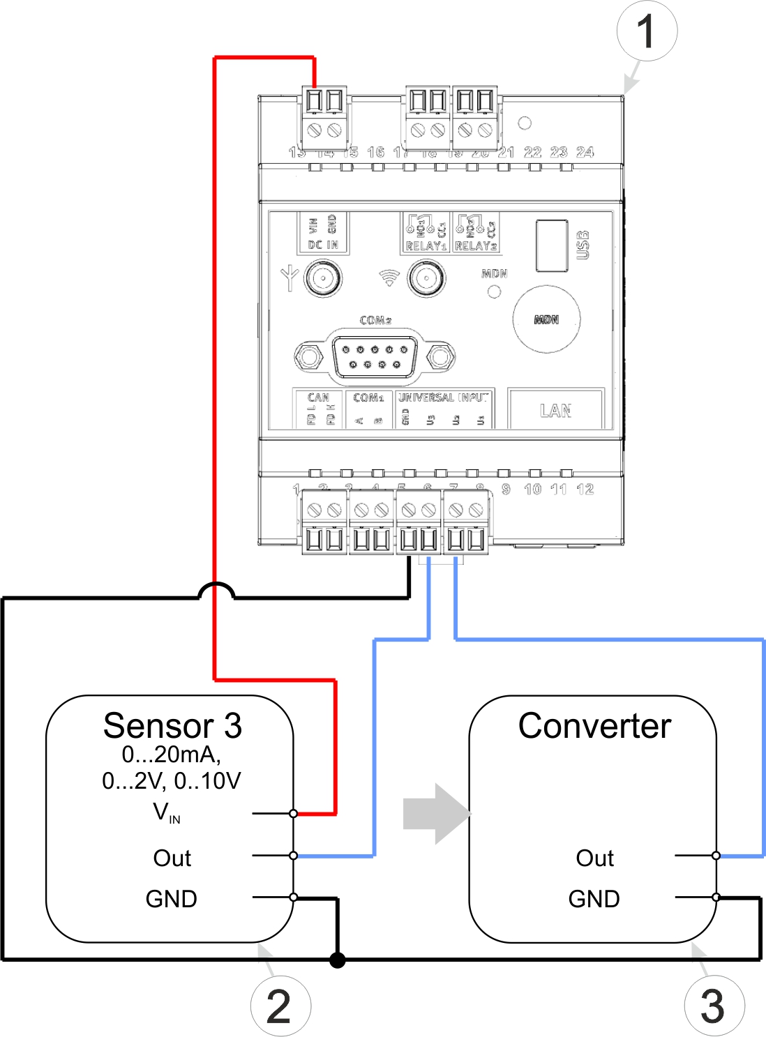
Connection examples (0...20 mA, 0...2 V, 0...10 V, converter)
| 1 | myDataconC3 MBM | 2 | Signal converter, isolating transducer |
| 3 | 3-wire mA sensor or 3-wire U-sensor |
A detailed explanation is provided in section Connection of the sensors, actuators and the supply.
Use a shielded twisted pair cable to prevent electromagnetic interference caused by the environment. The total length of the cables connecting the Modbus servers must not exceed 30 m. It is advisable to use a multi-core cable in which data and power lines can be routed together. When connecting multiple Modbus servers, only a bus structure is permitted. Stubs or star and tree topologies are not permitted.
A detailed explanation is provided in section Connection of the sensors, actuators and the supply.
Via the checkbox "termination" located in the input mask for configuring the modbus interface (see Modbus interface), the 120 Ω terminal resistance between RS485 A and B can be activated. In the same input mask, the checkbox "bias" can be found, which is used to activate the 390 Ω clamp resistances (Pull up to RS485 A and Pull down to RS485 B).
A detailed explanation is provided in section Technical details about the RS485 interface.
The myDataconC3 MBM does not have a special transport mode and therefore does not need to be deactivated.
A more detailed explanation is provided in section Storage of the product.
No.
The currently available variants of the myDataconC3 MBM are not equipped with a WiFi module. The port for the WiFi antenna is intended for future upgrades.
No.
The CAN interface is intended solely for connecting the extension modules.
No.
In the currently available variants of the myDataconC3 MBM , the necessary hardware is no longer installed. The visible LAN socket could only be used with the "myDatalogC33x WIFI/2G/3G/4G World", which is, however, no longer available.
The measurement data is assigned to the site and not to the linked device. If a device is replaced, all data (measurement values and configurations) are retained. The site is only assigned a different device by changing the serial number. From this moment on, the site receives the measurement data from the newly assigned device.
Proceed as follows to assign another myDataconC3 MBM to the site:
- Make sure the new device is disconnected from the power supply so that it cannot connect to the server.
- Open the default input screen for configuring the site (click on the pencil symbol in the list of sites, see "Sites / Applications" area at customer level).
- Enter the serial number of the new device in the "Device S/N" field of the configuration section "Site".
- If the device to be replaced is not online, trigger a connection (see Button). All data that has not yet been transmitted is transferred to the server.
- Check whether all relevant data has been transferred. If necessary, trigger the connection again.
- Connect the new device to the power supply. The connection should be established automatically.
- If the connection has not been established automatically, trigger a connection on the new device to transfer the the configuration of the site (and therefore also the assignment to the site) to the new device.
- Disconnect the device to be replaced from the power supply.
From this point on, the site receives the measurement data from the newly assigned device.


