Technical details about the RS485 interface
The RS485 interface of the myDataconC3 MBM includes an input common mode range that covers the full area specified for RS485 (-7 V...+12 V). Higher voltages damage the interface. Differential signals of more than +/-200 mV within the specified input common mode range are detected correctly. In send mode, the output signal is in the range of 1,5...3,3 V .
| Baud rate | 2400-115200 |
| Stop bits | 1, 2 |
| Parity | N, E, O |
| Data bits | 7, 8 |
| Load resistance |
Off 120 Ω |
| Terminal resistance |
Off 390 Ω |
Via the checkbox "termination" located in the input mask for configuring the modbus interface (see Modbus interface), the 120 Ω terminal resistance between RS485 A and B can be activated. In the same input mask, the checkbox "bias" can be found, which is used to activate the 390 Ω clamp resistances (Pull up to RS485 A and Pull down to RS485 B).
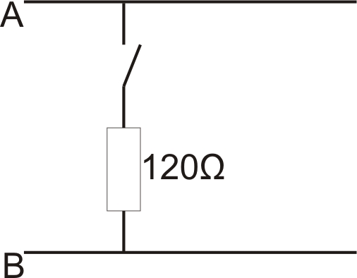
Schematic diagram of the switchable load resistances
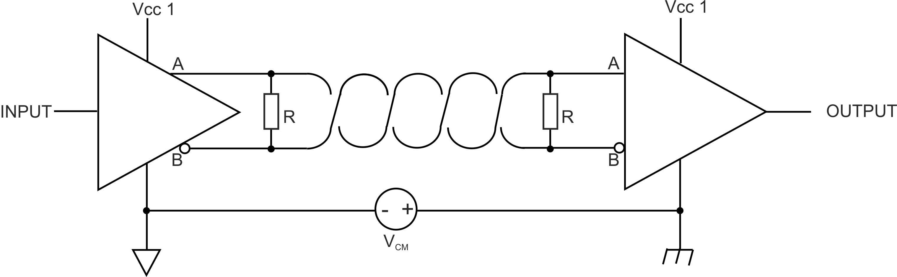
Schematic diagram: Connection of two RS485 bus participants
A problem occurs if there is no connection between the GND potentials of the sender and recipient. A common mode voltage (VCM) occurs in this case. The GND potential difference must not exceed max. +/- 7 V . Higher voltages will damage the interface. Temporary overvoltages (ESD, EFT and surge) are, however, absorbed by protective circuits.
Note: The common mode input voltage range of -7 V...+12 V specified for the RS485 is determined from the max. permissible GND potential difference (+/- 7 V ) and the max. permissible output voltage range of 0...5 V for RS485.


