Measurement channels
Configuration section to configure the settings for the 4 universal inputs and the external temperature sensor. The basic settings are configured in the "Basic" tab. The advanced configuration of the measurement channel is done via the "config" tab, whereas the available caonfiguration parameters depend on the "mode" selected in the "Basic" tab. The "Alarms" tab is used to set alarm thresholds and the "trigger" tab to determine the trigger thresholds as well as the actions to be performed in case the trigger conditions are met.
Basic
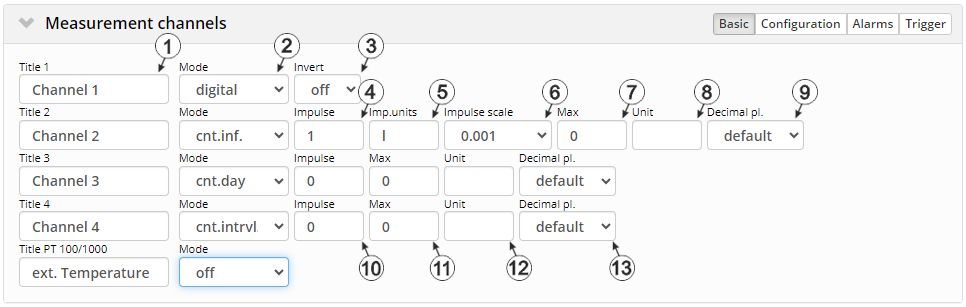
"Measurement channels" configuration section, "Basic" tab (digital mode & counter modes)
| 1 | Freely selectable channel title for the universal inputs
Freely selectable channel title for the external temperature sensor |
|
| 2 | Basic settings for the measurement channel | |
| off | Measurement channel deactivated | |
| on | Measurement channel activated (only for external temperature sensor) | |
| xxx | Analogue and digital modes (only for the universal inputs, see following table) | |
| 3 | Inverts the input signal |
| 4 | Counted measurand of a pulse in the "Imp. unit" |
| 5 | String, that specifies the measurement unit the impulses are delivered in |
| 6 | Factor with which the metered measurand of a pulse is multiplied to convert the "Imp. unit" to the "Unit" that is used by all of the display elements of the server (see Additional information on configuring a infinite counter:) |
| 7 | defines the upper end of the scale of the pointer instruments |
| 8 | String that is used as a measurement unit by all of the server display elements [0‑8 characters] |
| 9 | Number of decimal places that are used by all of the server display elements |
| 10 | Counted measurand of a pulse in the measurement unit |
| 11 | defines the upper end of the scale of the pointer instruments |
| 12 | String that is used as a measurement unit by all of the server display elements [0‑8 characters] |
| 13 | Number of decimal places that are used by all of the server display elements |
1) The day counter is reset to the time zone selected via the "time zone" parameter in the "basic settings" configuration section (see Basic settings) at 00:00 hours.
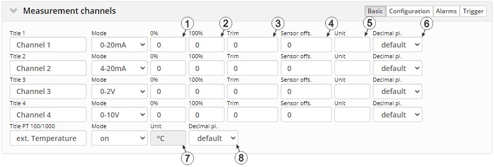
"Measurement channels" configuration section, "Basic" tab (analogue modes)
| 1 | Start of the measurement range in the measurement unit |
| 2 | End of the measurement range in the measurement unit |
| 3 | is used to adjust the zero point(see Additional explanation on the zero point adjustment and installation height of the sensor) |
| 4 | indicates the mounting height of the sensor |
| 5 | String that is used as a measurement unit by all of the server display elements [0‑8 characters] |
| 6 | Number of decimal places that are used by all of the server display elements |
| 7 | String that is used as measurement unit from all display elements of the server |
| 8 | Number of decimal places that are used by all of the server display elements |
Additional information on configuring a infinite counter:
Assumption: The meter provides one pulse per 5 l. The meter reading should be displayed in [m³] on the server interface
| Parameter | Value |
|---|---|
| Impulse | 5 |
| Imp.unit | l |
| Impulse scale | 0.001 |
| Unit | m³ |
Additional explanation on the zero point adjustment and installation height of the sensor
Assumption: Measurement range of the 4-20 mA pressure sensor 0-5 m

Installation situation of the pressure sensor
| 1 | Installation height: 15 cm | 3 | Output value of the sensor: 6 cm |
| 2 | Pressure sensor | 4 | Measured fill level: 20 cm |
| Parameter | Value |
|---|---|
| Mode | 4-20 mA |
| 0 % | 0 |
| 100 % | 5 |
| Trim | -0.01 |
| Sensor offset | 0.15 |
| Unit | m |
Explanation: When comparing the measured fill level with the output value of the sensor taking the installation height into consideration, it was determined that the value was 1 cm too high. As the "Trim" and "Sensor offset." parameters are added to the scaled measurement value, this error can be balanced out by setting the "Trim" parameter value to -0.01 m.
Configuration
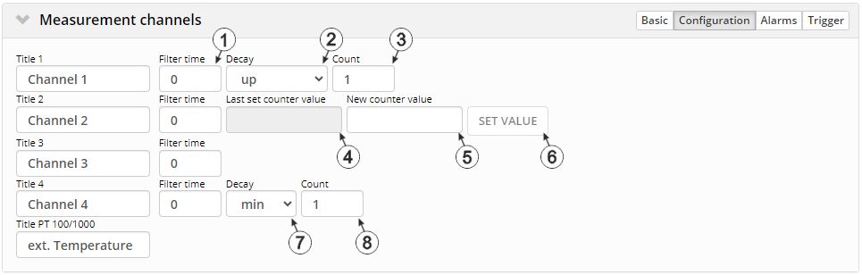
"Measurement channels" configuration section, "Configuration" tab (digital mode & counter modes)
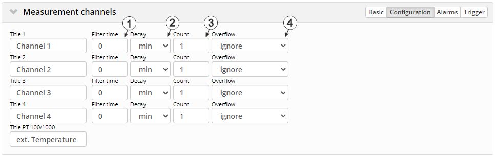
| 1 | Time in [ms] during which the signal must remain constant to initiate a level change. Used to suppress brief faults (debouncing). | |
| 2 | Temporal function in the measurement cycle | |
| off | Decay deactivated | |
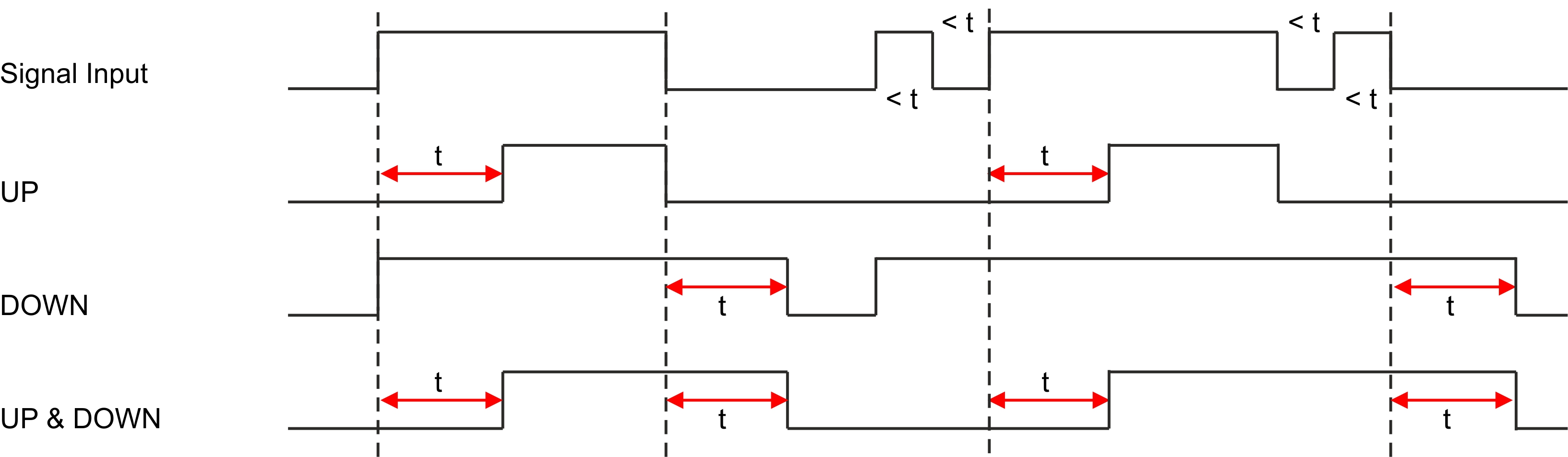
| up | At least x consecutive measurement values must be "High" for "High" to be recorded. | |
| down | At least x consecutive measurement values must be "Low" for "Low" to be recorded. | |
| up&down | At least x consecutive
measurement values must be "High" for "High" to be recorded.
At least x consecutive measurement values must be "Low" for "Low" to be recorded. |
|
|
||
| 3 | Number of measurement values taken into consideration during the decay (max. 64). In theses modes, a measurement value is created upon expiry of the measurement cycle and when the input signal level is changed. The changes to the inputs are monitored at one second intervals. | |
| 1 | Time in [ms] during which the signal must remain constant to initiate a level change. Used to suppress brief faults (debouncing). |
| 4 | Value to which the counter was set during the last change via the "Set value" button. Designed to check whether the device has correctly accepted the required counter reading. |
| 5 | Field for entering the new counter reading |
| 6 | Button for accepting the new counter reading. This button can only be operated if the device is in online mode or Aloha mode is active. |
| 1 | Time in [ms] during which the signal must remain constant to initiate a level change. Used to suppress brief faults (debouncing). |
| 1 | Time in [ms] during which the signal must remain constant to initiate a level change. Used to suppress brief faults (debouncing). | |
| 7 | Temporal function in the measurement cycle | |
| off | Decay deactivated | |
| min | The minimum of the last x measurement values is recorded. | |
| max | The maximum of the last x measurement values is recorded. | |
| avg | The arithmetic mean of the last x measurement values is recorded. | |
| med | The median of the last x measurement values is recorded. | |
| rms | The root mean square of the last x measurement values is recorded. | |
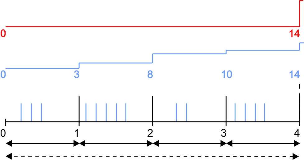
| sum | The pulses are added up and are not reset every time a measurement value is generated but only after the measurement value has been recorded. This mode is thus recommended if the record interval is longer than the measurement cycle. | |
| 8 | Number of measurement values taken into consideration during the decay (max. 64). This configuration parameter is not available if "sum" mode was selected for the decay. | |
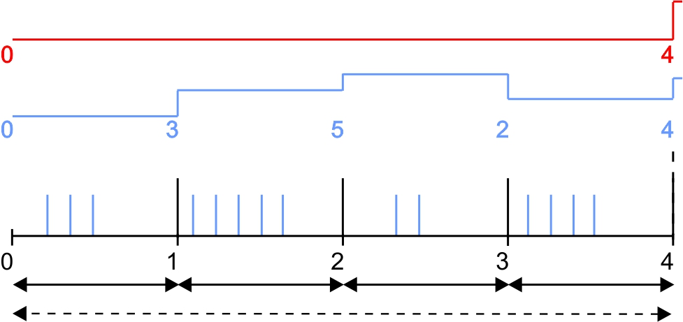
| Basic setting |
| Record interval | 4 min. | Recorded value | red line |
| Measurement cycle | 1 min. | Measurement value | blue line |

"Cnt.Intrvl." mode: The pulses are added up and reset every time a measurement value is generated. |
"Cnt.Day" mode: All of the pulses up to the reset time are added up. |
Note on "Cnt.Intrvl." mode: If the record interval is longer than the measurement cycle, by default only the number of pulses registered the last time the measurement value was generated is recorded. If all pulses within a record interval should be collected and recorded, “sum” mode must be selected for the decay. | |
"Measurement channels" configuration section, "Configuration" (analogue modes)
| 1 | Time in [ms] during which the analogue signal is averaged for signal smoothing. Used to suppress signal noise (also see Output channels). | |
| 2 | Temporal function in the measurement cycle | |
| off | Decay deactivated | |
| min | The minimum of the last x measurement values is recorded. | |
| max | The maximum of the last x measurement values is recorded. | |
| avg | The arithmetic mean of the last x measurement values is recorded. | |
| med | The median of the last x measurement values is recorded. | |
| rms | The root mean square of the last x measurement values is recorded. | |
| 3 | Number of measurement values taken into consideration during the decay (max. 64). | |
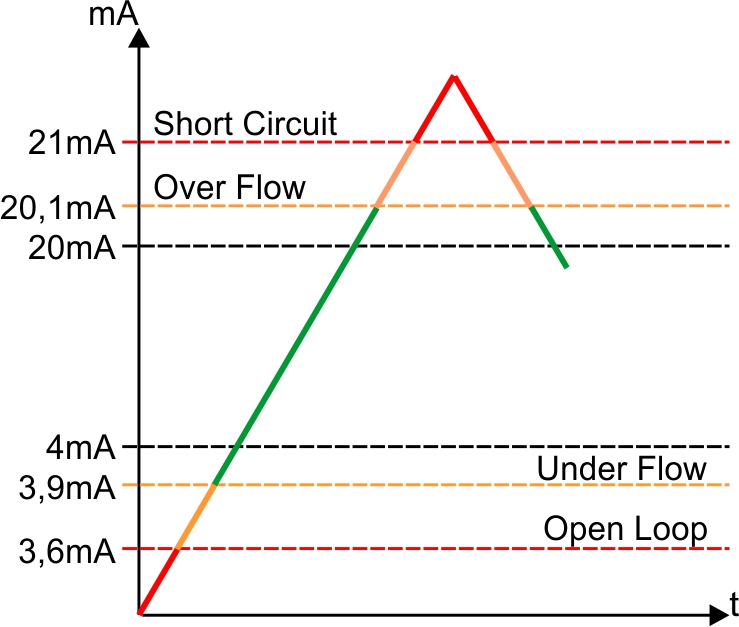
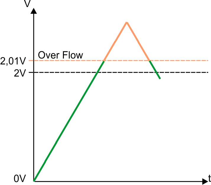
| 4 | Procedure in the event of measurement range violations | |
| Ignore | The measurement value is calculated beyond the range limits. | |
| Silent cutoff | The measurement value is truncated at the range limits. | |
| NAMUR borders |
Mode "0-20mA":
Mode "4-20mA":
Mode "0-2V":
Mode "0-10V":
|
|
Mode "0-20mA" |
Mode "4-20mA" |
Mode "0-2V" |
Mode "0-10V" |


Alarms

"Measurement channels" configuration section, "Alarms" tab
| 1 | A "high" at the universal input triggers a "warning". |
| 2 | A "high" at the universal input triggers an "alarm". |
| - | The alarms are not available for universal inputs that are operated in cnt.inf. mode. |
| 3 | A warning is triggered, if the measurement value drops to or below this value. |
| 4 | A warning is triggered, if the measurement value meets or exceeds this value. |
| 5 | An alarm is triggered, if the measurement value drops to or below this value. |
| 6 | An alarm is triggered, if the measurement value meets or exceeds this value. |
| 7 | Hysteresis for all-clear in event of alarm/warning (e.g. Hyst=5 %, alarm or warning at 100 -> all-clear at 95) |
Trigger
If an universal input is operated in digital mode, there are two different types of triggers:
- Event trigger (RI, XM)
In contrast to the level triggers, the relevant operation (e.g. record immediately) is only executed once when the trigger event occurs. With the help of the "Edge" configuration parameter, it is specified whether the rising, falling or both edges initiate the trigger event.
- Level trigger (ON, RA, OS, O3, OD, QX)
A "high" at the universal input initiates the trigger. A "low" at the universal input resets the trigger. The relevant operation (e.g. use alternative record interval) is executed as long as the trigger is active. The option selected via the "Edge" configuration parameter is not relevant to the level trigger. If it is necessary for the trigger to be initiated by a "low" at the universal input and for it to be reset by a "high", the input signal must then be inverted using the "Invert" configuration parameter located in the "Basis" tab.
These two types of triggers are also differentiated in other universal input modes with the exception of "cnt.inf." mode:
- Event trigger (RI, XM)
The relevant operation (e.g. initiate transmission) is only executed once when the trigger event occurs.
- Level trigger (ON, RA, OS, O3, OD, QX)
The relevant operation (e.g. activate online mode) is executed as long as the trigger is active.
The triggers are not available for universal inputs that are operated in "cnt.inf." mode.
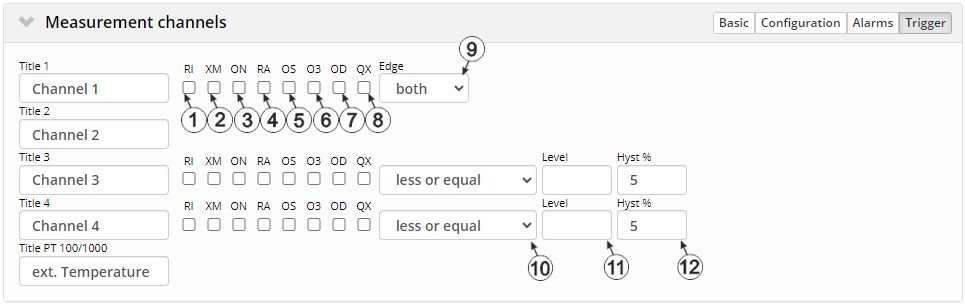
"Measurement channels" configuration section, "Trigger" tab
| Event trigger: | |
| 1 | Execute recording immediately |
| 2 | Initiate transmission |
| Level trigger: | |
| 3 | Activate online mode |
| 4 | The alternative record interval should be used. |
| 5 | If this checkbox has been selected, the setpoint at the switchable sensor supply output VOUT is controlled by the trigger function. The setpoint entered via the interface is ignored in that case. The output channel is normally set to "off (Low)" and switches to "on (High)" if trigger is active. However, if "invert" is active for the output channel, the procedure just described is reversed. The selected output voltage is taken into account in any case. See Example for explaining the release of the setpoint at the output via the trigger (output in "digital" mode). |
| 6 | If this checkbox has been selected, the setpoint at the switchable sensor supply output VEXT is controlled by the trigger function. The setpoint entered via the interface is ignored in that case. The output channel is normally set to "off (Low)" and switches to "on (High)" if trigger is active. However, if "invert" is active for the output channel, the procedure just described is reversed. |
| 7 |
Output in mode "digital": If this checkbox has been selected, the setpoint at the isolated switch contact (NO, CC) is controlled by the trigger function. The setpoint entered via the interface is ignored in that case.The output channel is normally set to "off (contact open)" and switches to "on (contact closed)" if trigger is active. However, if "invert" is active for the output channel, the procedure just described is reversed.Output in mode "Freq" or "Impulse": If this checkbox has been selected, the output of the frequency or the impulses/min at the isolated switch contact (NO, CC) is only released when trigger is active. When trigger is not active, the output channel is set to "off (contact open)". |
| 8 | The alternative transmission cycle should be used. |
| 9 | Event trigger: Selection of the edge at which the trigger should be initiated Level trigger: not relevant. The trigger is active as long as the measurement value is "High". |
|
| rising | The rising edge initiates the trigger. | |
| falling | The falling edge initiates the trigger. | |
| both | Both edges initiate the trigger. | |
| - | The triggers are not available for universal inputs that are operated in cnt.inf. mode. |
| - | The triggers are not available for the external temperature sensor. |
| 10 | Selection if the corresponding action is to be performed upon exceeding or falling below the value entered in the "level" field | |
| greater or equal |
Event trigger: The trigger is initiated if the measurement value meets or exceeds this value. Level trigger: The trigger is active as long as the measurement value is higher than the level or equal to the level. |
|
| less or equal |
Event trigger: The trigger is initiated if the measurement value drops to or falls below this value. Level trigger: The trigger is active as long as the measurement value is lower than the level or equal to the level. |
|
| 11 | Levels for initiating the trigger. The hysteresis is used to determine the level to reset the trigger. | |
| 12 | Hysteresis for revoking the trigger (e.g. hyst=5 %, level = greater or equal, trigger at 100 -> all-clear at 95) | |


