Output channels
Configuration section to configure the settings for the 2 switchable voltage outputs (supply of sensors) and the isolated switch contact (control of an actuator).
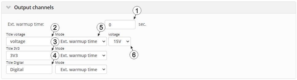
"Output channels" configuration section, mode "Ext. warmup time"
| 1 | Indicates the amount of time that an output channel is switched on in "Ext warmup time" mode before the measurement | |
| 2 | freely selectable designation for the output channel "switchable sensor supply (VOUT)" | |
| 3 | freely selectable designation for the output channel "switchable 3,3 V supply (VEXT)" | |
| 4 | freely selectable designation for the output channel "isolated switch contact (NO, CC)" | |
| 5 | Basic setting for the output channel
Note: Note that the power consumption increases significantly when "Freq" mode
is activated. When using a rechargeable battery pack (e.g. PSU413D+ AP ) or battery pack (e.g. PSU713
BP )
, the running time to be reached might thus be reduced to 1/6.
|
|
| Off | Output channel deactivated | |
| Ext. warmup time | The output channel is switched on "Ext. warmup time" seconds prior to the measurement. If the value is "0", the output channel is not switched on at all.The output channel is also turned on during Aloha transmission mode to ensure the determination of valid sensor readings. | |
| Digital | Digital output | |
| GPS 1) | Reserved for extensions | |
| Freq 2) | Frequency output | |
| Pulse 2) | Pulse output (pulse/min.) | |
| 6 | Selection of the output voltage 3) |
1) This mode is only available for switchable sensor supply output VEXT.
2) These modes are only available for the isolated switch contact (NO, CC).
3) Selection of the output voltage is only possible for the switchable sensor supply VOUT.
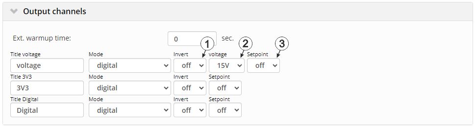
"Output channels" configuration section, "Digital" mode
| 1 | Inverts the level issued on the device |
| 2 | Selection of the output voltage 1) |
| 3 | Setpoint (on/off) that should be issued
Note: If one of the checkboxes "OS", "O3" or "OD" is selected in the
"Trigger" tab of the configuration sections "Measurement channels" or "Internal
channels", the "setpoint" entered here is ignored for the corresponding output
channel.
|
1) Selection of the output voltage is only possible for the switchable sensor supply VOUT.
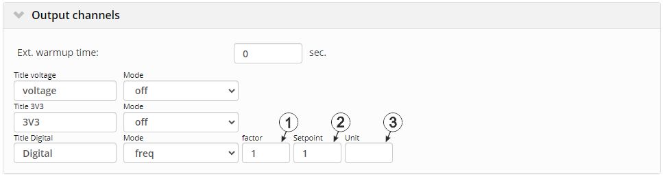
"Output channels" configuration section, "Freq" or "Pulse" mode
| 1 | The setpoint multiplied by the factor equals the frequency in Hertz. The result of the multiplication must not exceed 1000 Hz. |
| 2 | The setpoint multiplied by the factor equals the frequency in Hertz. The result of the multiplication must not exceed 1000 Hz. |
| 3 | String that is used as a measurement unit by all of the server display elements [0‑8 characters] |
| 1 | The setpoint multiplied by the factor equals the pulse/min. The result of the multiplication must not exceed 320 pulses/min. |
| 2 | The setpoint multiplied by the factor equals the pulse/min. The result of the multiplication must not exceed 320 pulses/min. |
| 3 | String that is used as a measurement unit by all of the server display elements [0‑8 characters] |
1) These modes are only available for the isolated switch contact (NO, CC).
Additional explanation on "Digital" mode
| Invert | Setpoint | Output on the device | |
|---|---|---|---|
| Off | Off | = | Off (low) |
| Off | On | = | On (high) |
| On | Off | = | On (high) |
| On | On | = | Off (low) |
Example to explain the filter time in conjunction with the Ext. warmup time
| Basic setting |

|
Record interval | 5min. |
|
Measurement cycle | 1min. | |
| Output channels |

|
Ext. warmup time | 1sec. |
| Measurement channels ->Config. |

|
Filter time | 500ms |
| Output on the device |

|
Sensor supply |

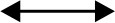
Explanation: The sensor supply is always activated 1sec before expiry of the measurement cycle. The filter time starts 500ms before expiry of the measurement cycle, which ensures that a valid value is available at the time of a measurement. However, this also means that the filter time must be taken into consideration when selecting the Ext. warmup time. In the current example, the sensor connected to the input must at the latest supply stable values 500ms following activation of the sensor supply. Otherwise, invalid values would be taken into consideration while averaging during the filter time resulting in the measurement value being distorted.
Example for explaining the release of the setpoint at the output via the trigger (output in "digital" mode)
| Basic settings |
|
Measurement cycle | 1min. |
| Measurement channels -> Trigger | OS | Selected | |
| Threshold | Greater or equal 100 |
||
| Hyst % | 5 | ||
| Output channels | Mode | Digital | |
| Invert | Off | ||
| Setpoint | On |
| Trigger not active |

|
Green line | |
| Trigger active |

|
Red line | |
| Output on the device |
|
Sensor supply | |

Initial situation:One of the measurement channels should be used to determine the switching state at the output channel depending on the measurement value using the trigger. If one of the checkboxes "OS" (switchable sensor supply VOUT), "O3" (switchable 3,3 V supply VEXT) or "OD" (isolated switch contact) in the "Trigger" tab of the "Measurement channels" configuration section (see Measurement channels) is selected for one of the measurement channels, the output of the setpoint for the corresponding output channel is set to "off (Low)".
Explanation: The output on the device is set to "off (Low)" up to the time of 2, as the measurement value on the measurement channel is below the trigger level. The trigger is active from the time of 2, which sets the ouput to "on (High)". At the time of 3, the output channel is ultimately set to "off (Low)" again as the measurement value falls below the "Level - hyst" value (100-5=95).
Additional specification: If one of the checkboxes ("OS", "O3" or "OD") is selcected, the "setpoint" entered via the interface is ignored for the corresponding output channel. However, the parameter "invert" is taken into account. If "invert" is active for the output channel, the switching states at the output are exactly reversed compared to the example above (i.e. the output channel is set to "on (High)" with inactive trigger). For the ouput channel "switchable sensor supply (VOUT)", the parameter "Voltage" (i.e. the selection of the output voltage) is also considered.
Example for explaining the release of the setpoint at the output via the trigger (output in "Freq" or "Pulse" mode)
| Basic settings |
|
Measurement cycle | 1 min. |
| Measurement channels -> Trigger | OD | Selected | |
| Threshold | Greater or equal 100 |
||
| Hyst % | 5 | ||
| Output channels | Mode | Freq | |
| Factor | 5 | ||
| Setpoint | 10 |
| Trigger not active |
|
Green line | |
| Trigger active |
|
Red line | |
| Output on the device |
|
Isolated switch contact | |
Initial situation: To begin with, the output channel "isolated switch contact (NO, CC)" is configured so that the desired frequency is output at the isolated switch contact of the device. For this purpose, the mode "Freq" is selected and the frequency is defined via the parameters "Factor" and "Setpoint" (the setpoint multiplied by the factor gives the frequency in Hertz). Subsequently, one of the measurement channels is to be used to release the frequency output depending on the measurement value using the triggers. If the "OD" (isolated switch contact) checkbox is selected in the "Trigger" tab of the "Measurement channels" configuration section (see Measurement channels) for one of the measurement channels, the output of the frequency for the isolated switch contact is blocked at the time of the next measurement, provided the trigger for this measurement channel is not active. The switch contact is open and remains in this state.
Explanation: The isolated switch contact is inactive up to the time of 2, as the measurement value on the measurement channel is below the trigger level. The trigger is active from the time of 2, which releases the ouput of the frequency at the output. The switch contact is continuously opened and closed at the set frequency. At time 3, the frequency output is ultimately disabled again as the measurement value falls below the "Threshold - Hyst" value (100-5=95). The switch contact is open and remains in this state.
Additional specification: If the "isolated switch contact (NO, CC)" output channel is operated in "Pulse" mode, the behaviour is similar to that described above. In this case, the "Factor" and "Setpoint" parameters are used to specify how many pulses per minute are to be output. Between times 2 and 3, instead of a frequency pulses are output via opening and closing the switch contact in this mode.


