Online help for 4-Channel Data Logger on myDatalogEASY IoTmini
General product information
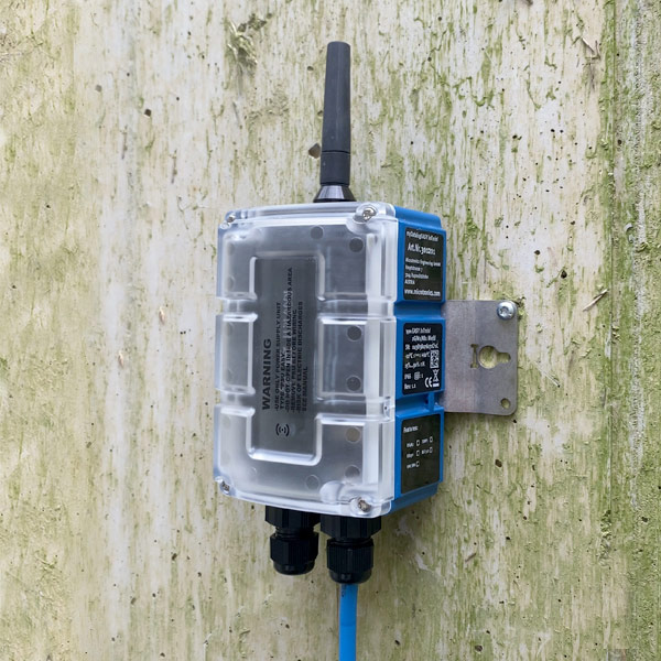
The 4-Channel
Data Logger is a data logger designed for stand-alone operation.

Product characteristics:
- Universal inputs for digital and analogue signals
- Switchable and adjustable supply voltage for sensors
- Isolated switch contact
- Internal battery compartment
- Battery, rechargeable battery or direct power supply
- Exactstate of charge of the battery using Coulombmethod
- Compact design
- Integrated charge control
- Configurable via web interface
- Device time synchronised with the sever
- Hardware real-time clock
- Very low commissioning & operating costs
- Integrated durable SIM chip
Application:
- Level measurement
- Flow measurement
- Temperature measurement
- Transmission of measurement values of probes
- Remote meter reading
This online help is applicable from:
Frequently asked questions (FAQs)
 What do the blink codes mean?
| Blink code | Colour | Description |
|---|---|---|
| 0x | --- | Transport lock (transmission OFF, measurement OFF) |
| 1x | green | Last connection OK |
| 2x | red | Last transmission faulty |
| 7x | red | Network block/no matching provider |
| 8x | red | No mobile network |
| 9x | red | incorrect PIN/1 attempt remaining |
| 10x | red | No mobile network connection |
| 11x | red | No server available |
| 12x | red | Faulty SIM chip |
A detailed explanation is provided in section Three colour status LED.
How do I initiate a connection?

|
| How-To-Video: Triggering Aloha transmission mode |
Tap theMDN Magnet (206.803) for at least 3 sec. on the position shown in the following figure.
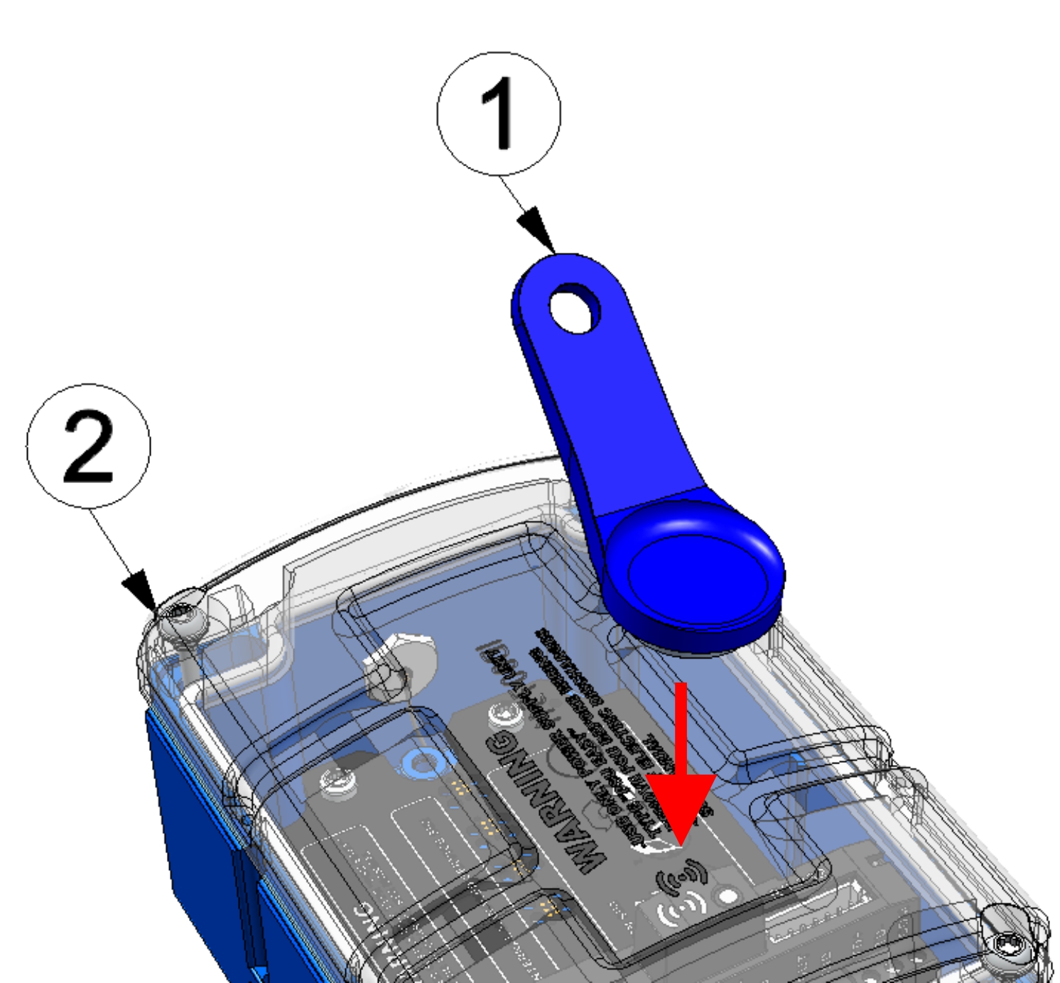
| 1 | MDN Magnet (206.803) | 2 | 4-Channel Data Logger |
How do I activate the output of the error codes / status codes?
Briefly (approx. 1 sec.) tap theMDN Magnet (206.803) on the position shown in the following figure.
How do I connect a 0/4-20 mA sensor?
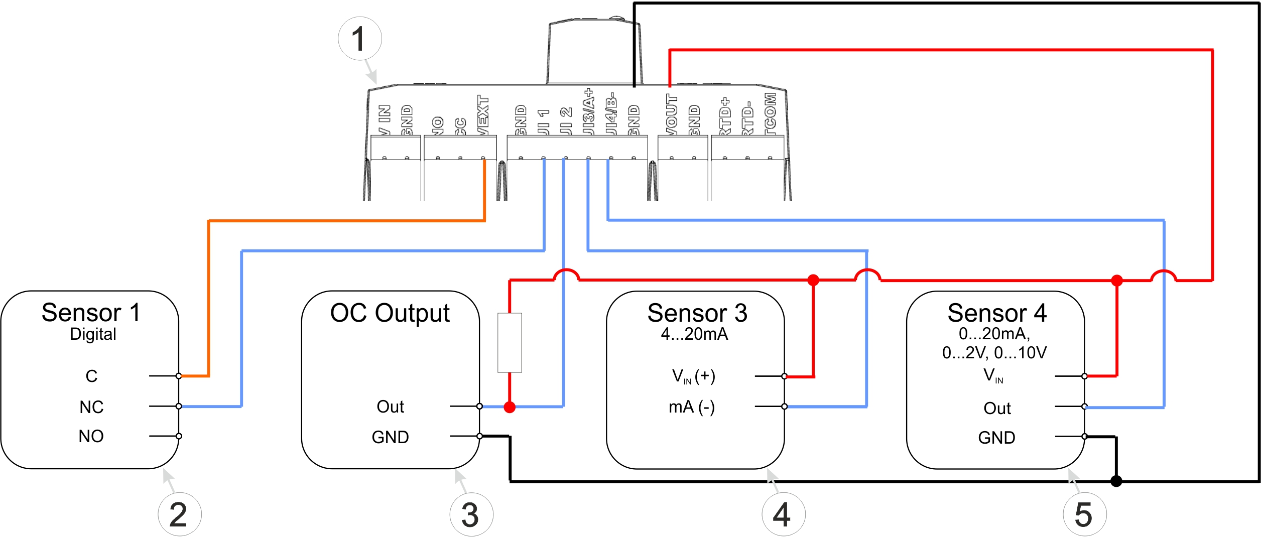
Connection examples (digital, open collector output, 0/4...20 mA, 0...2/10 V)
| 1 | Main terminal block of the 4-Channel Data Logger | 4 | 2-wire mA sensor |
| 2 | Isolated relay contact | 5 | 3-wire mA sensor or 3-wire U-sensor |
| 3 | Sensor with open collector output |
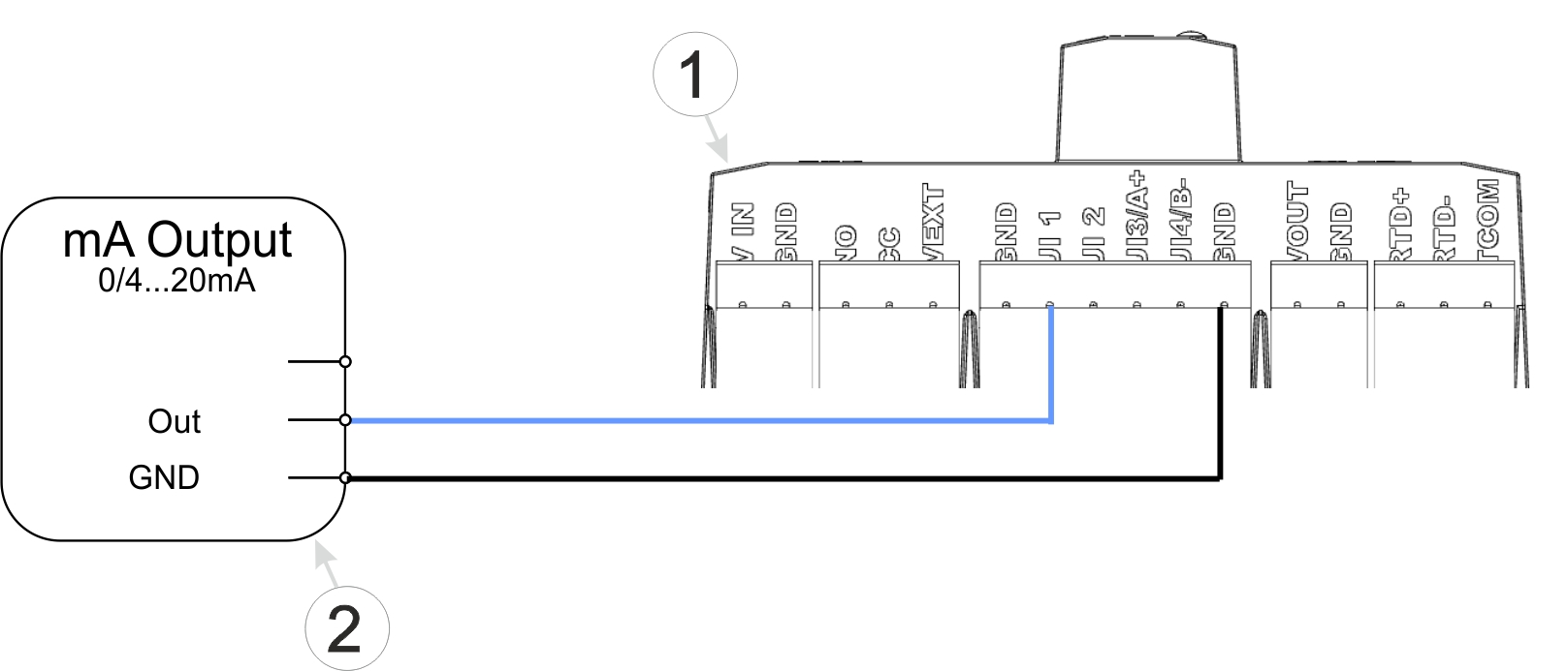
Connection examples (active mA output)
| 1 | Main terminal block of the 4-Channel Data Logger | 2 | Active mA output, transducer or isolation transformer |
A detailed explanation is provided in section Connecting the sensors, actuators and power supply.
Which sensors are compatible with the 4-Channel
Data Logger ?
Microtronics Engineering GmbHis constantly testing various sensors with mA output for compatibility with the4-Channel Data Logger .
A list of compatible sensors is provided in section Compatible sensors.
How do I deactivate the 4-Channel
Data Logger again?
Activate transport mode by setting the "operating mode" in the "Basic settings" configuration section (see Basic settings) to "transport". After that, initiate a connection (see Aloha transmission mode) to transmit the changed configuration to the 4-Channel Data Logger .
A detailed explanation is provided in section Storage of the product.
How can I assign a different 4-Channel
Data Logger to the site? I.e. how do I replace a device?
The measurement data is assigned to the site and not to the linked device. If a device is replaced, all data (measurement values and configurations) are retained. The site is only assigned a different device by changing the serial number. From this moment on, the site receives the measurement data from the newly assigned device.
Proceed as follows to assign another 4-Channel Data Logger to the site:
- Make sure that no PSU is inserted in the new device, so that it cannot connect to the server.
- Open the default input screen for configuring the site (click on the pencil symbol in the list of sites, see "Sites / Applications" area at customer level).
- Enter the serial number of the new device in the "Device S/N" field of the configuration section "Site".
- Trigger a connection on the device to be replaced (see Solenoid switch).All data that has not yet been transmitted is transferred to the server.
- Check whether all relevant data has been transferred. If necessary, trigger the connection again.
- Connect the new device to the power supply (optional for PSUs with integrated energy storage).
- Insert a PSU in the new device. The connection should be established automatically.
- Trigger a connection on the new device to transfer the the configuration of the site (and therefore also the assignment to the site) to the new device.
- Disconnect the device to be replaced from the power supply.
From this point on, the site receives the measurement data from the newly assigned device.