Testing communication with the device
- Create a new site/application based on the "4-Channel Data Logger" application for operation on the myDatanet server (see Creating the site).
- Configure the created site/application according to your requirements (see Site configuration).
- Connect the antenna (see Connecting the mobile network antenna). The antenna is not included in the scope of delivery and must be ordered separately.
- Insert the power supply unit. It is designed in such a way that it cannot be inserted
incorrectly.
Tip: If you are using a power supply unit without an integrated energy store, the external supply or charging voltage must be connected before inserting the power supply unit. Details on this are provided in the chapter Connecting the sensors, actuators and power supply.

Inserting the power supply unit
1 Power supply unit 2 Base unit - Initiate Aloha transmission mode (see Aloha transmission mode) so that
the configuration of the site is transmitted to the 4-Channel
Data Logger .

How-To-Video: Triggering the Aloha transmission mode
- Wait until it is indicated in the list of measurement instruments that the device is in Aloha transmission mode. This is indicated by a speech bubble with the "Aloha" inscription.
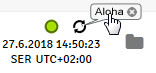
- Stop Aloha transmission mode by clicking the cross in the speech bubble with the "Aloha" inscription or wait for the duration of Aloha transmission mode. This period can be set in the basic settings (see Basic settings) of the site settings. The default setting is 10 minutes.
- Complete all of the steps detailed in the chapter Assembling the 4-Channel
Data Logger . This includes connecting the sensors.
Important: All wiring work must be performed in the de-energised state.
- Check the incoming data in the Aloha data window of the myDatanet server, which can be accessed by clicking on
the speech bubble with the "Aloha" inscription (see "myDatanet Server Manual " 805002). Particular attention
must be paid to the "GSM" and "SOC" measurement values.
"SOC" specifies the state of charge of the energy source integrated in the power
supply unit.
Tip: Additional explanation about evaluating the "Signal strength of the mobile network":
"Mobile signal strength" >-64 dBm 
-64 to -73 dBm 
-74 to -83 dBm 
-84 to -93 dBm 
-94 to -107 dBm 
<= -108 dBm 
The following steps are only necessary, if you simultaneously want to test the measurement value acquisition and data transmission.


