Assembling the 4-Channel Data Logger
- All wiring work must be performed in the de-energised state.
- Ensure installation is completed correctly.
- Improper handling can cause injuries and/or damage to the instruments.
- The 4-Channel Data Logger must not be operated in the field with the lid open.
- To ensure the housing is properly sealed, each of the cable screw connections must only hold a single cable.
The 4-Channel Data Logger is split into several components when delivered and must therefore be assembled before use.

Components of the 4-Channel Data Logger
| 1 | Connector plug (2x 2-pin, 2x 3-pin, 1x 6-pin) | 5 | 4x Delta PT M3,5x25 Torx 15 |
| 2 | Power supply unit (not included in scope of delivery) | 6 | Housing cover |
| 3 | 2x cable glands (cable diameter of 5-10 mm) | 7 | Blind plugs |
| 4 | 4-Channel Data Logger base unit |
- Check that the content of the pack is complete.
- Insert the SIM card in the SIM slot as described in chapter Inserting/replacing the SIM card. Obviously,
the first steps to open the housing and remove the power supply unit are not
necessary.
Note: The chargeable feature "Activation code VPN SIM (300539)" must be released to be able to use the SIM slot.
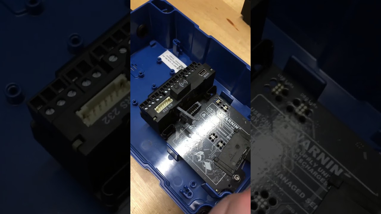
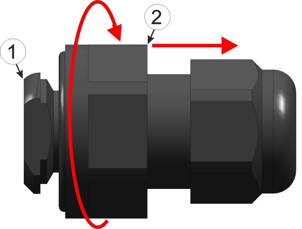
How-To-Video: Inserting the SIM card - Turn the locking nut of the cable screw connection clockwise (left-hand thread) to the stop to increase the distance between the locking nut and engagement hook and thus make it easier to insert the cable screw connection into the hole in the 4-Channel Data Logger base unit. The engagement hook is not symmetrical. One of the lugs on the engagement hook is longer.
- First of all thread the connection cables of your sensors, actuators and, if necessary,
the supply or charging voltage through one of the cable screw connections in accordance
with the following figure, and then through one of the holes in the 4-Channel
Data Logger base unit. Then connect the cables to the
connector plugs as described in chapter Connecting the sensors, actuators and power supply. Depending on how flexible the cables are, it may be advantageous to
connect them to the connector plugs before the connector plugs are inserted in to the 4-Channel
Data Logger base unit.
Important: Only a single cable must be threaded through the cable screw connections to ensure the seal of the housing is not jeopardised.
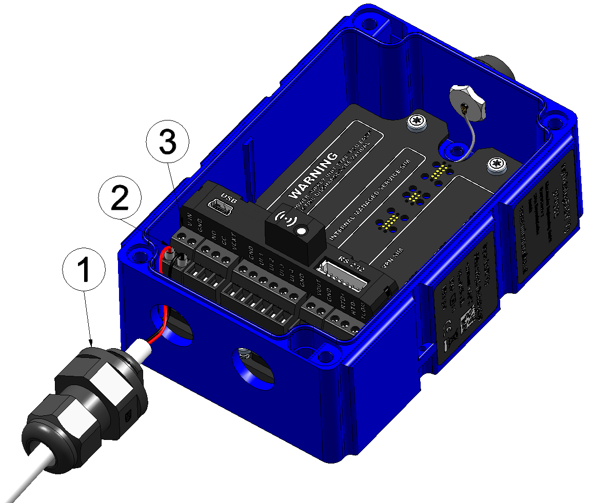
Threading the connection cables in
1 Cable screw connection (cable diameter of 5-10 mm) 3 Connector plug (2x 2-pin, 2x 3-pin, 1x 6-pin) 2 Connection cable of a sensor, actuator or the supply or charging voltage - In accordance with the following figures, thread the engagement hook with the side that
has the longer lug first (see Fig. 2 -
preparing the cable screw connection)
through the hole in the 4-Channel
Data Logger base unit. The cables
that have already been threaded in are not illustrated in this figure in the interests of
clarity.
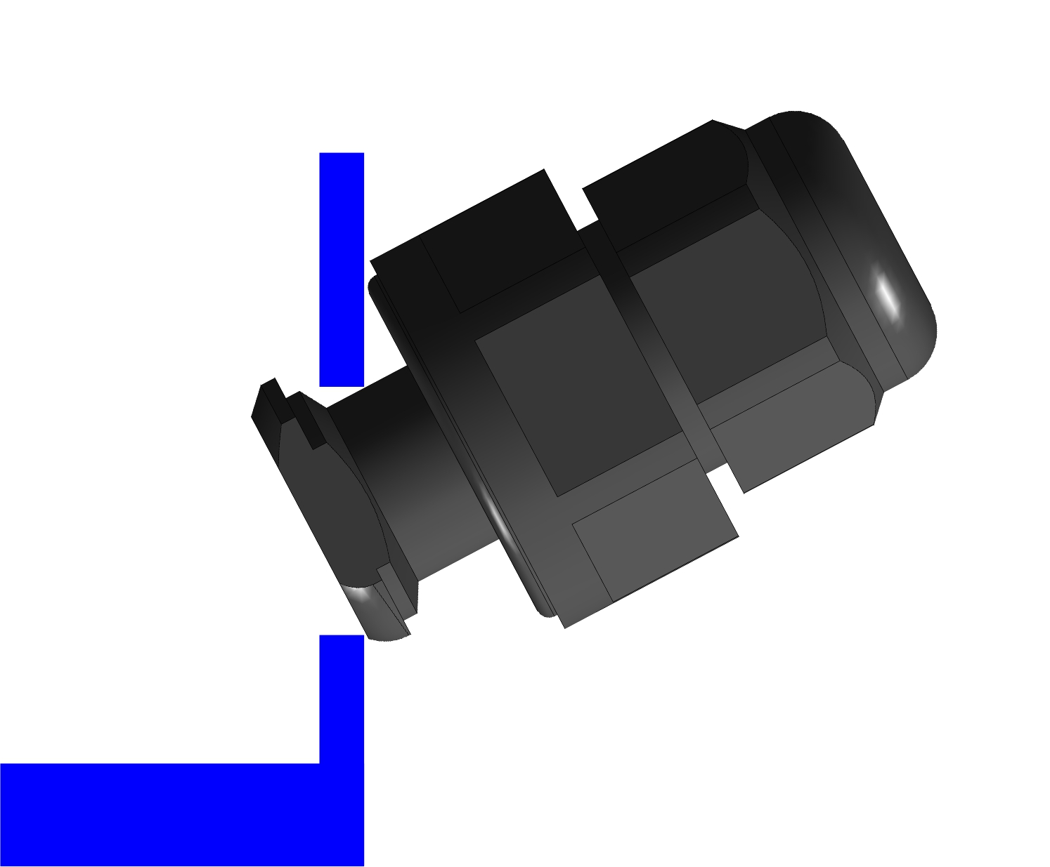
Fig. 1 - threading in the cable screw connection
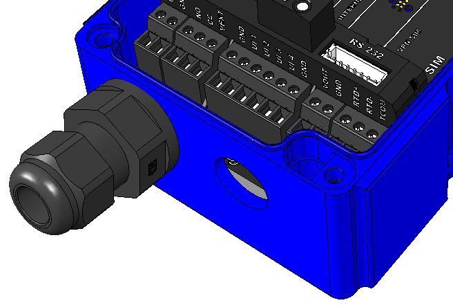
Fig. 2 - threading in the cable screw connection
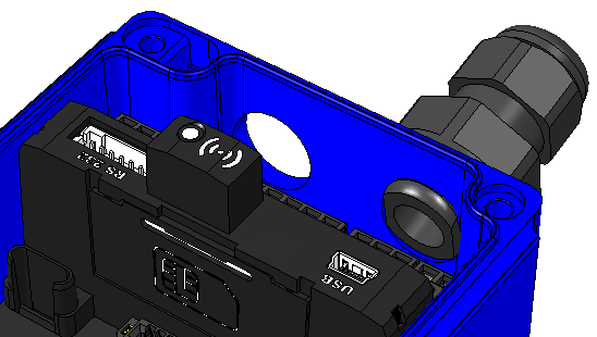
Fig. 3 - threading in the cable screw connection
- Tighten the locking nut by turning it counterclockwise (left-hand thread).
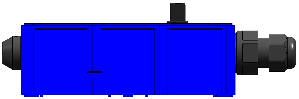
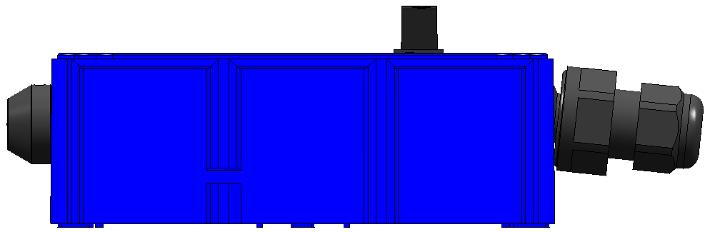
Important: Ensure that the seal is clean and intact before tightening. Remove any impurities and/or dirt. The manufacturer shall not be liable for any damage to the device caused by leaky or faulty seals.
- Check that the seal for the cable screw connection is positioned correctly on all sides
and that no foreign materials have been trapped between the housing, seal and locking
nut.
Important: The manufacturer is not liable for any damage that is caused by seals that are not positioned correctly.


- Connect the antenna (see Connecting the mobile network antenna). The antenna is not included in the scope of delivery and must be ordered separately.
- Insert the power supply unit. The power supply unit is designed in such a way that it
cannot be inserted incorrectly.
Tip: Note that all power supply units with an integrated and rechargeable energy store are delivered with a maximum charge of 30% in accordance with applicable transport regulations and must therefore be fully charged before being used for the first time (see Charging the power supply unit).
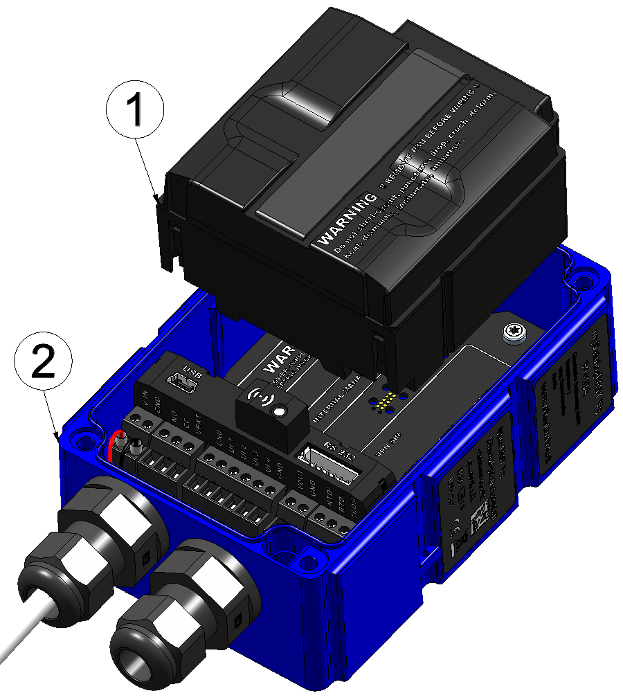
Inserting the power supply unit
1 Power supply unit 2 4-Channel Data Logger base unit - Check whether the connection to the myDatanet server has worked correctly (see Testing communication with the device).
- Close the housing cover. The best option is to tighten the four screws crosswise
(torque 0,5 Nm; At the first screw 0,7 Nm because the threads have to be shaped into the base part first.) so that
the housing cover is positioned evenly.
Important: Ensure that the seals are clean and intact before closing the housing cover. Remove any impurities and/or dirt. The manufacturer shall not be liable for any damage to the device caused by leaky or faulty seals.
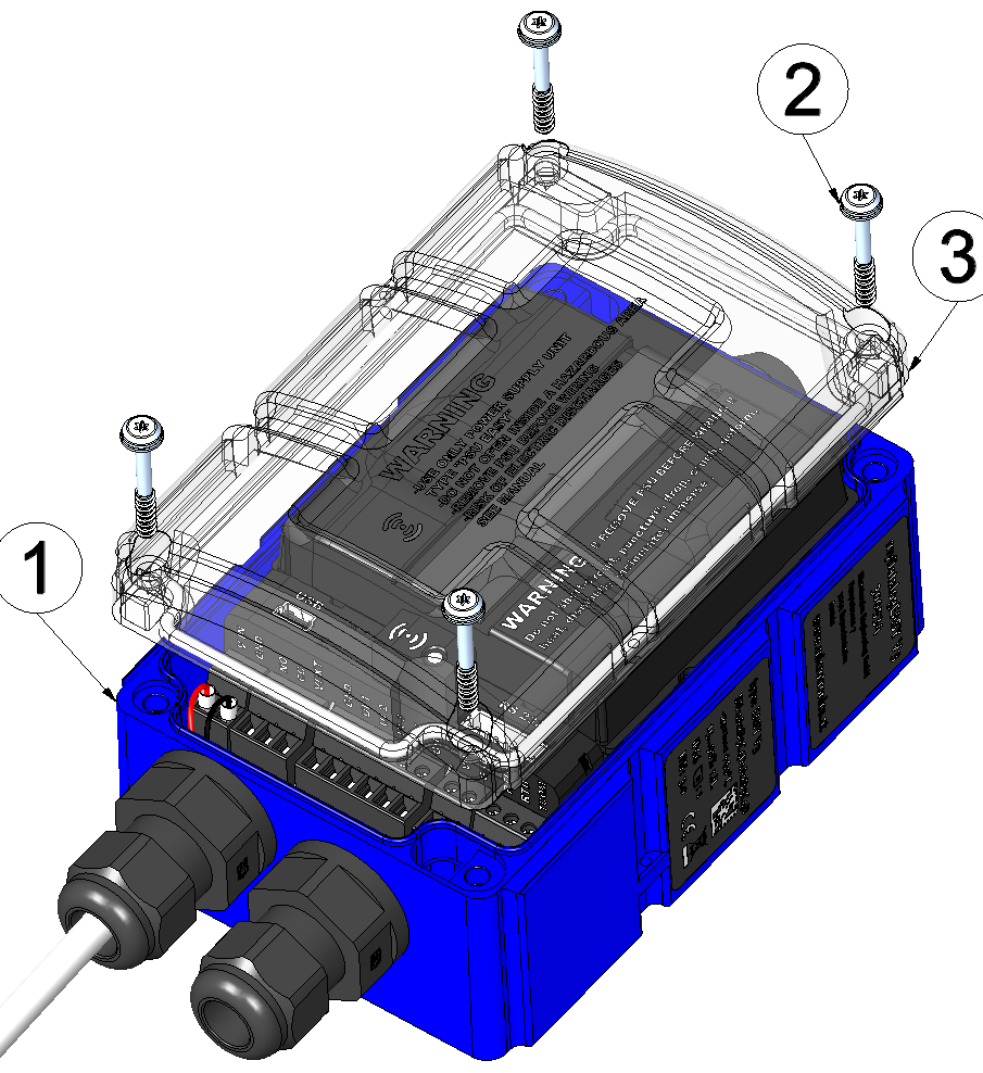
Closing the housing cover
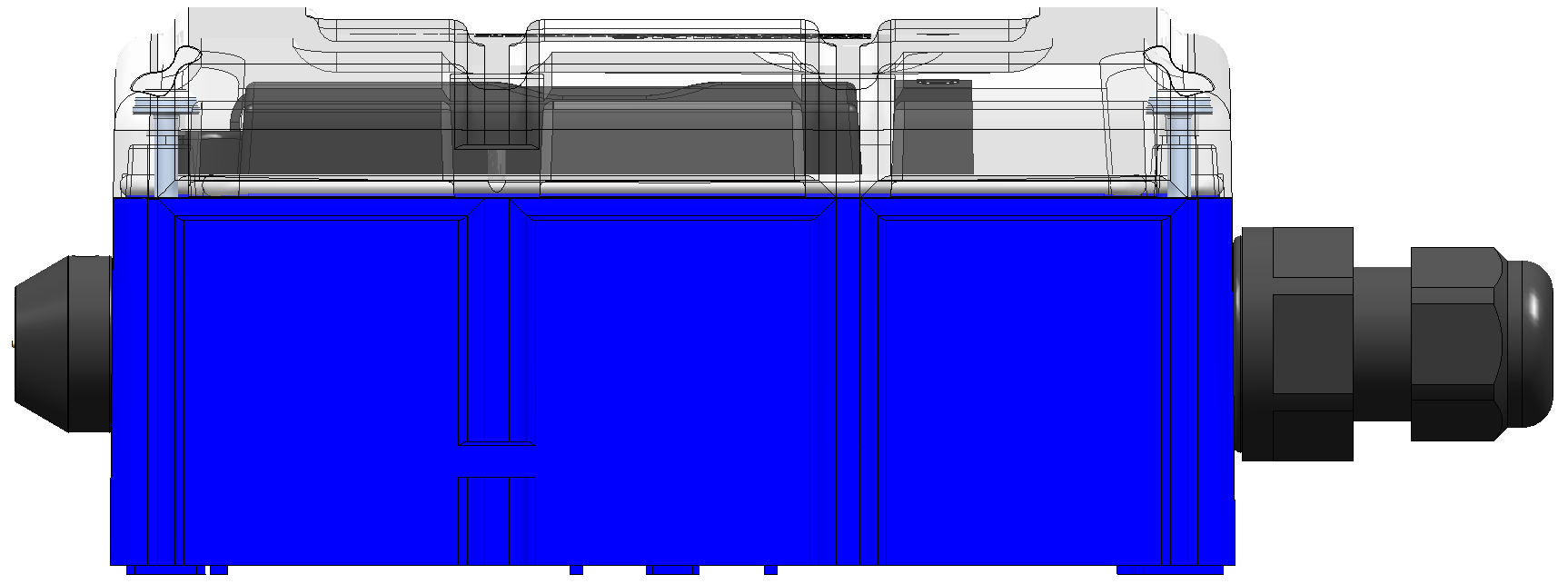
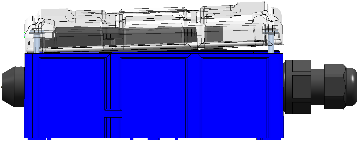
1 4-Channel Data Logger base unit 3 Housing cover 2 Delta PT M3,5x25 Torx 15 - Check that the housing cover is positioned correctly on all sides and that no foreign
materials have been trapped between the housing and housing cover.
Important: The manufacturer is not liable for any damage that is caused by housing covers that are not closed correctly.
- Now switch on the external supply or charging voltage.
Tip: If you are using a power supply unit without an integrated energy store, the external supply or charging voltage must be switched on before the optional step during which the connection to the server is tested.