Modbus measurement channels
Configuration section to configure the settings for the 20 modbus measurement channels. The basic settings are configured in the "Basic" tab. The "Configuration" tab is used to determine from which modbus registers the data is received and how the data stored in the modbus registers is to be interpreted. The "Scale" tab allows for the read out raw data to be resecaled into the desired unit. The "Alarms" tab is used to set the alarm thresholds and the "Trigger" tab to determine the trigger thresholds as well as the actions to be performed in case the trigger conditions are met.
Basic
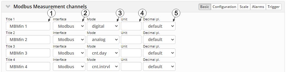
"Modbus measurement channels" configuration section, "Basic" tab
| 1 | freely selectable channel designation for the modbus measurement channels | |
| 2 | Basic settings for the modbus measurement channel | |
| off | Measurement channel deactivated | |
| Modbus | The data for the measurement channel are determined usint the RS485 interface selected in the configuration section "Modbus interface". The interface is always configured as modbus client (formerly master) in "RTU" operating mode. | |
| 3 | defines how the modbus measurement channel is to be handled by the report elements of the server | |
| digital | Digital measurement value. I.e. the system considers each measurement value independently from the measured values before or after. | |
| analogue | Analogue measurement value. I.e. the system considers each measurement value independently from the measured values before or after. | |
| Cnt.Day | Day counter. This means that the system anticipates that the measurement value of the channel will continuously increase and is reset once per day. | |
| Cnt.Intervl | Interval counter. This means that the system assumes that the counter reading is reset each time a measurement is recorded. | |
| 4 | String that is used as a measurement unit by all of the server display elements [0‑16 8 characters] | |
| 5 | Number of decimal places that are used by all of the server display elements | |
Configuration
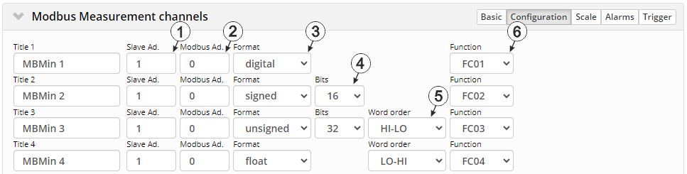
"Modbus measurement channels" configuration section, "Configuration" tab
| 1 | Address of the modbus server | |
| 2 | Address of the register that should be read | |
| 3 | Format in which the data to be read is stored in the register | |
| Digital | A digital value should be read. | |
| Signed | A signed integer value should be read. | |
| Unsigned | The integer value to be read is not signed. | |
| Float | A 32-bit float should be read. | |
| 4 | Selection of the word length (i.e. number of bits the integer value consists of)
Only available if "Signed" or "Unsigned" has been selected for the format (i.e. an integer value should be read from the register) |
|
| 16 |
16-bit integer |
|
| 32 |
32-bit integer. Two registers must be read from the modbus server for this purpose. |
|
| 5 | Selection of the word order, if the selection of format and word length requires that 2 registers are read from the modbus server (i.e. "Float", "Signed" with a word length of 32 bit or "Unsigned" with a word length of 32 bit has been selected) | |
| HI-LO |
HI word on the lower register address and the LO word on the higher register address |
|
| LO-HI |
LO word on the lower register address and the HI word on the higher register address |
|
| 6 | Function code to be used for accessing the register | |
| FC01 | Read Coils | |
| FC02 | Read Discrete Inputs | |
| FC03 | Read Holding Registers | |
| FC04 | Read Input Registers | |
Scale
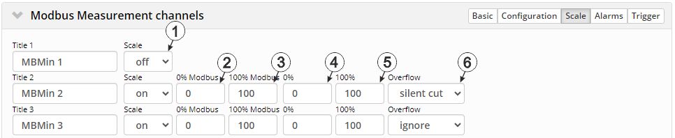
"Modbus measurement channels" configuration section, "Scale" tab
| 1 | Selection if the raw data read from the register is to be rescaled before further processing. | |
| off | The data is processed unchanged.. | |
| on | Scale active (i.e. the data is rescaled into the desired unit before further processing) | |
| 2 | Start of the measurement range in the unit of the modbus server (i.e. raw value to be read from the modbus server) | |
| 3 | End of the measurement range in the unit of the modbus server (i.e. raw value to be read from the modbus server) | |
| 4 | Start of the measurement range in the measurement unit | |
| 5 | Start of the measurement range in the measurement unit | |
| 6 | Procedure in the event of measurement range violations | |
| Ignore | The measurement value is calculated beyond the range limits. | |
| Silent cutoff | The measurement value is truncated at the range limits. | |
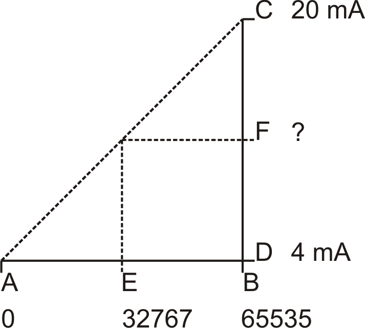
| 0 % | 4 mA | D |
| 100 % | 20 mA | C |
| 0 % Modbus | 0 | A |
| 100 % Modbus | 65535 | B |
| Measurement value in the unit of the modbus server | 32767 | E |
| Scaled measurement value | 11,9998 mA | F |
| F = ( (C - D)/(B - A) ) * (E - A) + D F = ( (20 mA - 4 mA) /(65535 - 0) ) * (32767 - 0) + 4 mA =11,9998 mA |
Alarms
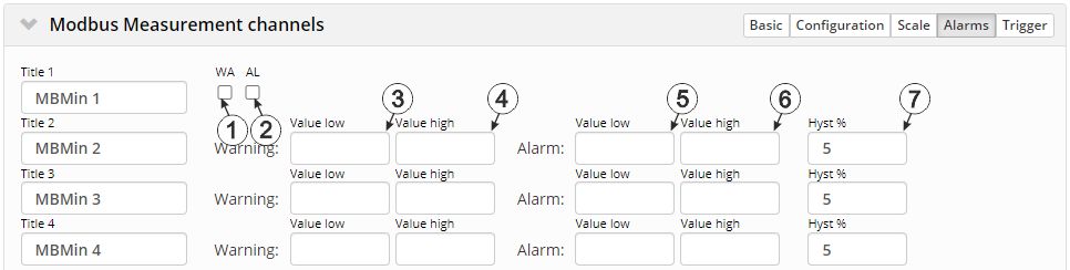
"Modbus measuement channels" configuration section, "Alarms" tab
Which of the configuration parameters are available for the respective modbus measurement channel depends on the format selected via the "Configuration" tab in which the data to be read is saved in the register.
| 1 | A "high" at the universal input triggers a "warning". |
| 2 | A "high" at the universal input triggers an "alarm". |
| 3 | A warning is triggered, if the measurement value drops to or below this value. |
| 4 | A warning is triggered, if the measurement value meets or exceeds this value. |
| 5 | An alarm is triggered, if the measurement value drops to or below this value. |
| 6 | An alarm is triggered, if the measurement value meets or exceeds this value. |
| 7 | Hysteresis for all-clear in event of alarm/warning (e.g. Hyst=5 %, alarm or warning at 100 -> all-clear at 95) |
Trigger
There are two different types of triggers:
- Event trigger (RI, XM)
The relevant operation (e.g. initiate transmission) is only executed once when the trigger event occurs.
- Level trigger (ON, QX)
The relevant operation (e.g. use alternative record interval) is executed as long as the trigger is active.

"Modbus measurement channels" configuration section, "Trigger" tab
| Event trigger: | |
| 1 | Execute recording immediately |
| 2 | Initiate transmission |
| Level trigger: | |
| 3 | Activate online mode |
| 4 | The alternative record interval should be used. |
| 5 | The alternative transmission cycle should be used. |
Which of the configuration parameters are available for the respective modbus measurement channel depends on the format selected via the "Configuration" tab in which the data to be read is saved in the register.
| 9 | Event trigger: Selection of the edge at which the trigger should be initiated Level trigger: not relevant. The trigger is active as long as the measurement value is "High". |
|
| rising | The rising edge initiates the trigger. | |
| falling | The falling edge initiates the trigger. | |
| both | Both edges initiate the trigger. | |
| 10 | Selection if the corresponding action is to be performed upon exceeding or falling below the value entered in the "level" field | |
| greater or equal |
Event trigger: The trigger is initiated if the measurement value meets or exceeds this value. Level trigger: The trigger is active as long as the measurement value is higher than the level or equal to the level. |
|
| less or equal |
Event trigger: The trigger is initiated if the measurement value drops to or falls below this value. Levelt rigger: The trigger is active as long as the measurement value is lower than the level or equal to the level. |
|
| 11 | Levels for initiating the trigger. The hysteresis is used to determine the level to reset the trigger. | |
| 12 | Hysteresis for revoking the trigger (e.g. hyst=5 %, level = greater or equal, trigger at 100 -> all-clear at 95) | |


