Modbus output channels
Configuration section to configure the settings for the 12 modbus output channels. The basic settings are configured in the "Basic" tab. The "Configuration" tab is used to determine in which modbus register the setpoints should be written and in which format the setpoints should be filed in the corresponding registers. Via the "Scale" tab, the setpoints available in a specific unit can be rescaled to the desired raw value to be written into the register.
Basic
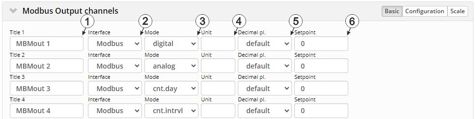
"Modbus output channels" Configuration section, "Basic" tab
| 1 | freely selectable designation for the modbus output channels | |
| 2 | Basic setting for the modbus output channel | |
| off | Output channel deactivated | |
| Modbus | The setpoint is transmitted to the modbus server via the RS485 interface selected in the "Modbus interface" configuration section. The interface is always configured as modbus client (formerly master) in "RTU" operating mode. | |
| 3 | defines how the modbus output channel is to be handled by the report elements of the server | |
| digital | Digital measurement value. I.e. the system considers each measurement value independently from the measured values before or after. | |
| analogue | Analogue measurement value. I.e. the system considers each measurement value independently from the measured values before or after. | |
| Cnt.Day | Day counter. This means that the system anticipates that the measurement value of the channel will continuously increase and is reset once per day. | |
| Cnt.Intervl | Interval counter. This means that the system assumes that the counter reading is reset each time a measurement is recorded. | |
| 4 | String that is used as a measurement unit by all of the server display elements [0‑16 8 characters] | |
| 5 | Number of decimal places that are used by all of the server display elements | |
| 6 | Output value in the measurement unit | |
Configuration
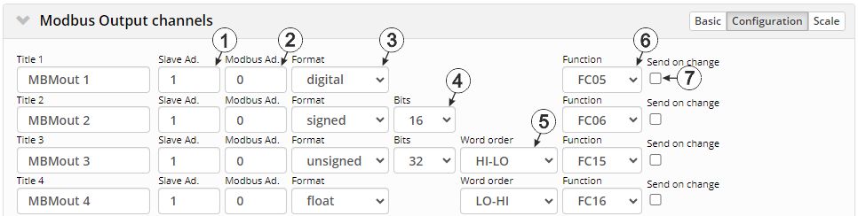
"Modbus output channels" configuration section, "Configuration" tab
| 1 | Address of the modbus server | |
| 2 | Address of the register that should be written to | |
| 3 | Format in which the setpoint is to be written to the register | |
| digital |
A digital value must be written. |
|
| signed |
A signed integer value should to be written. |
|
| unsigned |
The integer value to be written is not signed. |
|
| float |
A 32-bit float should to be written. |
|
| 4 | Selection of the word length (i.e. number of bits the integer value consists of)
Only available if "signed" or "unsigned" has been selected for the format |
|
| 16 |
16-bit integer |
|
| 32 |
32-bit integer. Two registers must be written in the modbus server for this purpose. |
|
| 5 | Selection of the word order, if the selection of format and word length requires that 2 registers are written to the modbus server (i.e. "Float", "Signed" with a word length of 32 bit or "Unsigned" with a word length of 32 bit has been selected) | |
| HI-LO |
HI word on the lower register address and the LO word on the higher register address |
|
| LO-HI |
LO word on the lower register address and the HI word on the higher register address |
|
| 6 | Function code to be used for accessing the register | |
| FC5 | Write Single Coils | |
| FC6 | Write Single Register | |
| FC15 | Write Multiple Coils | |
| FC16 | Write Multiple Registers | |
| 7 |
Selected: In the event of a change, the setpoint is only transmitted to the modbus server once after the current measurement value has expired.1) Not selected: The setpoint is transmitted to the modbus server cyclically in the measurement interval. 2) |
|
1) Recommended if the modbus server saves the received data in a non-volatile memory each time. It prevents the int. flash of the modbus server from reaching the max. number of write cycles prematurely due to frequent writing of the same data.
2) Recommended if the modbus server uses the continuous data transmission to recognise if the connection to the modbus client is still active.
Scale
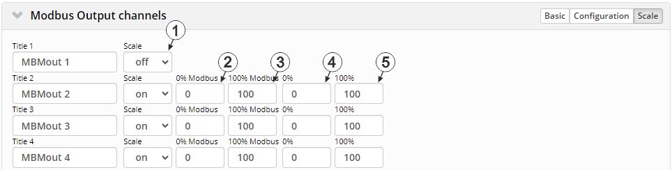
"Modbus output channels" configuration section, "Scale" tab
| 1 | Selection if the setpoint is to be rescaled before writing it to the register. | |
| off | The setpoint is written to the register as is. | |
| on | Scale active (i.e. the setpoint is rescaled into the desired raw value before writing it to the register) | |
| 2 | Start of the output range in the unit of the modbus server (i.e. the raw value to be written in the modbus server) | |
| 3 | End of the output range in the unit of the modbus server (i.e. the raw value to be written in the modbus server) | |
| 4 | Start of the output range in the measurement unit | |
| 5 | End of the output range in the measurement unit | |
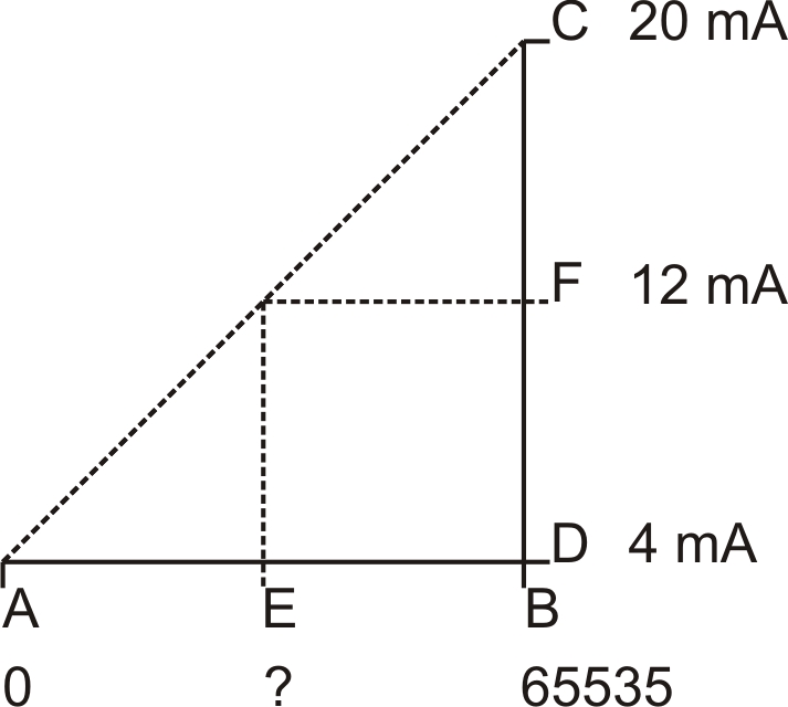
| 0 % | 4 mA | D |
| 100 % | 20 mA | C |
| 0 % Modbus | 0 | A |
| 100 % Modbus | 65535 | B |
| Basic > setpoint | 12 mA | F |
| Scaled output value | 32767 | E |
| E = ( (B - A)/(C - D) ) * (F - D) + A F = ( (65535 - 0) /(20 mA - 4 mA) ) * (12 mA - 4 mA) + 0 =32767 |