Basic settings
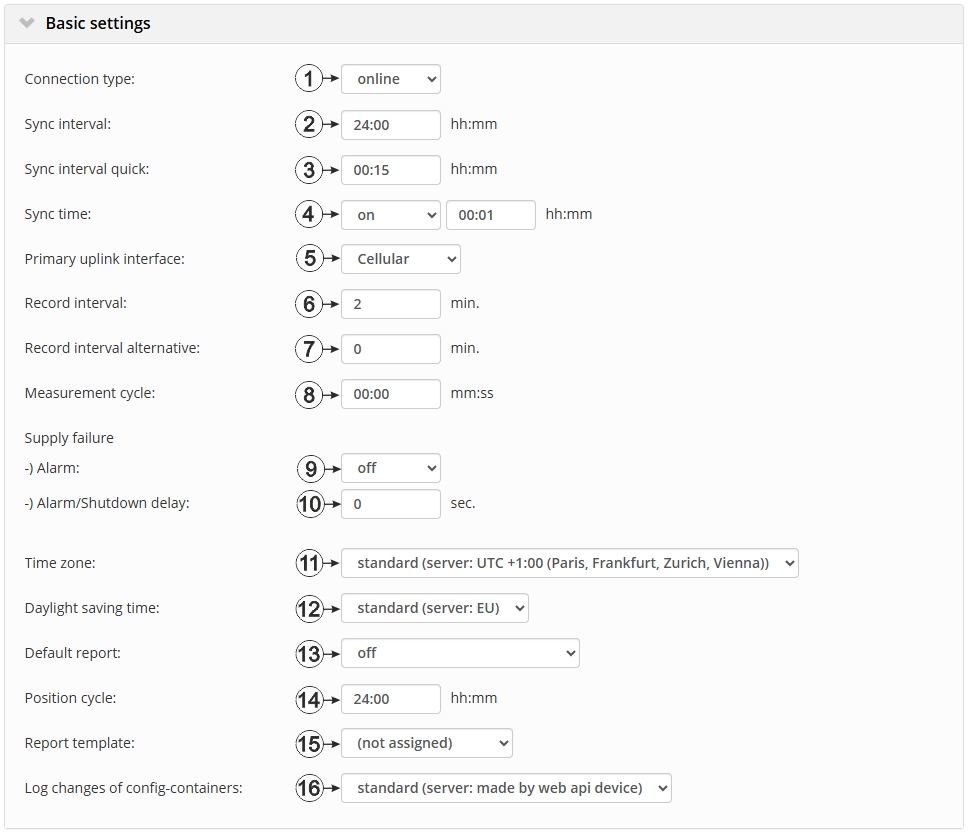
"Basic settings" configuration section
| 1 | Selection of the connection
type With this selection, the labels of the three subsequent input fields are also adjusted. |
|
| Interval | The device connects in the transmission cycle.
Lables used for the input fields: "Transmission cycle", "Transmission cycle quick" and "Transmission time" |
|
| online | The device does not disconnect the connection and continuously
transmits the measurement data. However, every 7 days, the connection is
temporarily interrupted in order to verify the server assignment.
Lables used for the input fields:: "Syn. interval", "Sync interval quick" and "Sync time" |
|
| 2 | Time between transmissions . Upon established online connection, a complete device synchronisation is carried out instead of a connection establishment. | |
| 3 | Time between the transmissions, if a alternative transmission cycle should be used because of a trigger being initiated.Upon established online connection, a complete device synchronisation is carried out instead of a connection establishment. | |
| 4 | Selection of whether a connection to the server should be established every day at a firmly defined time | |
| off | No additional transmissions | |
| on | The adjacent option can be used to determine the time at which the device establishes a connection to the server regardless of the transmission cycle.Upon established online connection, a
complete device synchronisation is carried out instead of a connection
establishment.
If an additional transmission has been initiated, the internal meter of the device, that determines the time of the transmission, is reset. This means that the next transmission is completed exactly after the time specified via the "transmission cycle" parameter. |
|
| 5 | Selection of the preferred communication channel | |
| Cellular | Initially an attempt is made to establish a mobile network connection. | |
| 6 | Time between measurement data recordings | |
| 7 | Time between measurement data recordings, if an alternative record interval should be used because of a trigger being initiated | |
| 8 | Time between measurements (00:00 same as record interval) | |
| 9 | Selection of whether an alarm should be triggered in the event of a supply voltage failure | |
| off | No alarm generated in the event of a supply voltage failure | |
| on | An alarm shall be generated in the event of a supply voltage failure | |
| 10 |
If the offset of a failure report is deactivated: The device is only completely deactivated if the supply voltage has failed for longer than the time configured here. This prevents the device from shutting down in the event of brief supply voltage failures. However, an entry is always added to the device log. If the time is set to 0, the device is immediately completely deactivated every time the supply voltage fails. If setting off a failure report is activated: A relevant alarm is only triggered if the supply voltage has failed for longer than the time configured here. This prevents alarms from being triggered in the event of brief supply voltage failures. However, an entry is always added to the device log.If the time is set to 0, an alarm is generated every time the supply voltage fails. |
|
| 11 | Regional settings (not relevant for raw measurement data as this is stored in UTC) | |
| 12 | Configuration for automatic time adjustment (only displayed if a time zone other than "Standard" has been selected) | |
| Standard | The configuration for the time adjustment is adopted by the global server setting (see "myDatanet Server Manual " 805002). | |
| Off | Automatic time adjustment deactivated | |
| USA | Predefined setting for the American area | |
| EU | Predefined setting for the European area | |
| 13 | Selection of the report that is loaded by clicking on the device link in the maps | |
| Off | The default graphic is loaded. | |
| "Name of a report" | The selected report is loaded. | |
| 14 | Position update interval (00:00 positioning is completed with every connection) | |
| 15 | Selection of whether the default graphic or a report template to display the data is used when clicking on the symbol to display the measurement data located in the site/application list. Only the report templates in which the site/application type of the first wild card is compatible with the site/application that is currently being edited are displayed in the dropdown list. | |
| (not assigned) | The default graphic is used to display the measurement data. | |
| "Name of a report template" | Name of the report template used to display the measurement data | |
| 16 | Selection of which changes to the configurations should be logged | |
| web api | Changes that were implemented via the server interface or REST-API are logged. | |
| web device api | Changes that were implemented via the server interface, by the device itself or the REST-API are logged. | |
| Connection type | Energy consumption | Data volumes | Response time |
|---|---|---|---|
| online |  |  |  |
| Interval | | | |


