Output channels
Configuration section to configure the settings for the 2 relays.

Configuration section "Output channels"
| 1 | freely selectable designation for the output channels | |
| 2 | Basic setting for the output channel | |
| off | Output channel deactivated | |
| digital | Digital output | |
| 3 | Inverts the level issued on the device |
| 4 | Setpoint (on/off) that should be issued
Note: If one of the check boxes "D1" or "D2" is selected in the
"Trigger" tab of the configuration section "Measurement channels" or
"Internal channels", the
"setpoint" entered is ignored for the corresponding output channel.
|
Additional explanation on "Digital" mode
| Invert | Setpoint | Output on the device | |
|---|---|---|---|
| Off | Off | = | Off (low) |
| Off | On | = | On (high) |
| On | Off | = | On (high) |
| On | On | = | Off (low) |
Example explaining how to determine the switching state at the output via trigger
| Basic settings |
|
Measurement cycle | 1 min. |
| Measurement channels -> Trigger | D1 | Selected | |
| Threshold | Greater or equal 100 |
||
| Hyst % | 5 | ||
| Output channels | Mode | digital | |
| Invert | off | ||
| Setpoint | on |
| Trigger not active |

|
green line | |
| Trigger active |

|
red line | |
| Output on the device |

|
Switching state |
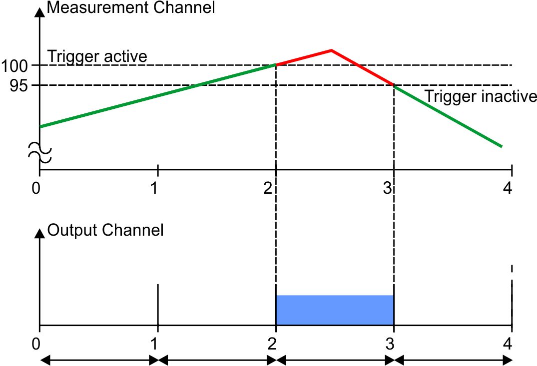
Initial situation: One of the measurement channels is to be used to determine the switching state at the ouput channel depending on the measurement value using the triggers. If one of the checkboxes "D1" (output channel "RELAY1") or "D2" (output channel "RELAY2") in the "Trigger" tab of the "Measurement channels" configuration section (see Measurement channels ) is selected for one of the measurement channels, the output channel is set to "off (Low)" at the time of the next measurement as long as the trigger for this measurement channel is not active.
Explanation: The output on the device is set to "off (Low)" up to the time of 2, as the measurement value on the measurement channel is below the trigger level. The trigger is active from the time of 2 which sets the output to "on (High)". At the time of 3, the output is ultimately set to "off (Low)" again as the measurement value falls below the "Level - hyst" value (100-5=95).
Ergänzung: If one of the two checkboxes ("D1" or "D2") has been selected, the "setpoint" entered for the relevant output channel via the interface is ignored. The parameter "invert" is however taken into account. If "invert" is active for the output channel, the switching states at the output are exactly the opposite of the example described above (i.e. with trigger active, the output channel is set to "on (High)").


