Online help for myDataconC3
General product information
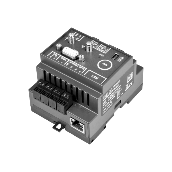
ThemyDataconC3 is a compact, stationary measurement system designed for installation in control cabinets. In addition to recoding and transferring analogue or digital signals, it can be used for control and regulating tasks. The measurement system requires a continuous power supply. However, the data logger has an integrated rechargeable buffer battery which allows sending a notification in the event of a voltage supply failure. Thanks to the 3 universal inputs that can be operated in various analogue or digital modes, the myDataconC3 is compatible with a large number of different sensors. Furthermore 2 x relays are available to control actuators, of which the setpoints can be determined wirelessly from a central point. The measurement data of the inputs are determined in an adjustable interval and together with the states of the outputs they are temporarily stored in an internal data memory. This stored data is sent to a central server for further processing in a freely selectable interval using the mobile network. The measurement system is equipped with an integrated SIM chip for establishing a mobile connection. By using the mobile network to transfer data to the server, the site rarely has to be physically accessed and the data can be accessed at all times.
Product characteristics:
- Universal inputs for digital and analogue signals
- Relay outputs
- Integrated rechargeable buffer battery to issue a message in the event of a power supply failure
- Measurement value storage on the device
- Data transmission to the server via mobile network
- Location-independant management of the measurement sites via internet
- Adjustable record and transmission interval
- Device time synchronised with the sever
- Hardware real-time clock
- Very low commissioning & operating costs
- Integrated durable SIM chip
Application:
- Data collection
- Transmission of measurement values of probes
- Asset monitoring
- Alarm monitoring
This online help is applicable from:
- Firmware version: 02v009
- IoT app version: 17v000
- Server version: 54v00x
- Product revision: 1.2 (M1/NB1 EU) / 1.7 (2G/4G World)
Frequently asked questions (FAQs)
| Blink code | Colour | Description |
|---|---|---|
| 1x | green | Last connection OK |
| 2x | red | Last transmission faulty |
| 7x | red | Network block/no matching provider |
| 8x | red | No mobile network |
| 10x | red | No mobile network connection |
| 11x | red | No server available |
| 12x | red | Faulty SIM chip |
A detailed explanation is provided in section Status LED.
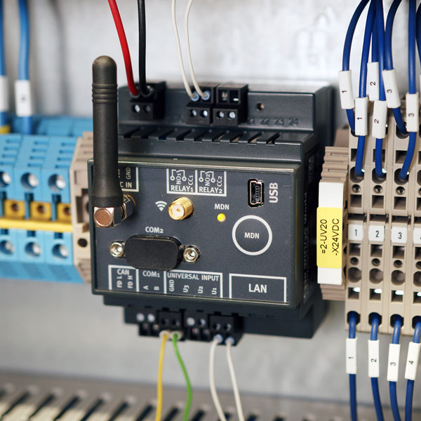
When the power supply is connected, the device automatically establishes a connection. The status LED initially flashes green to indicate that a connection is being established. Once the connection has been established, the status LED remains lit green.
If the connection has been interrupted, you can initiate the connection manually by holding down the "MDN" button for at least 3 seconds. You can recognise that there is currently no connection by the fact that the status LED is either off or displaying one of the error/status codes (see Status LED).
Regardless of the connection type selected (online or interval), the myDataconC3 will automatically attempt to re-establish the connection if it is lost (see Procedure in case of connection aborts).
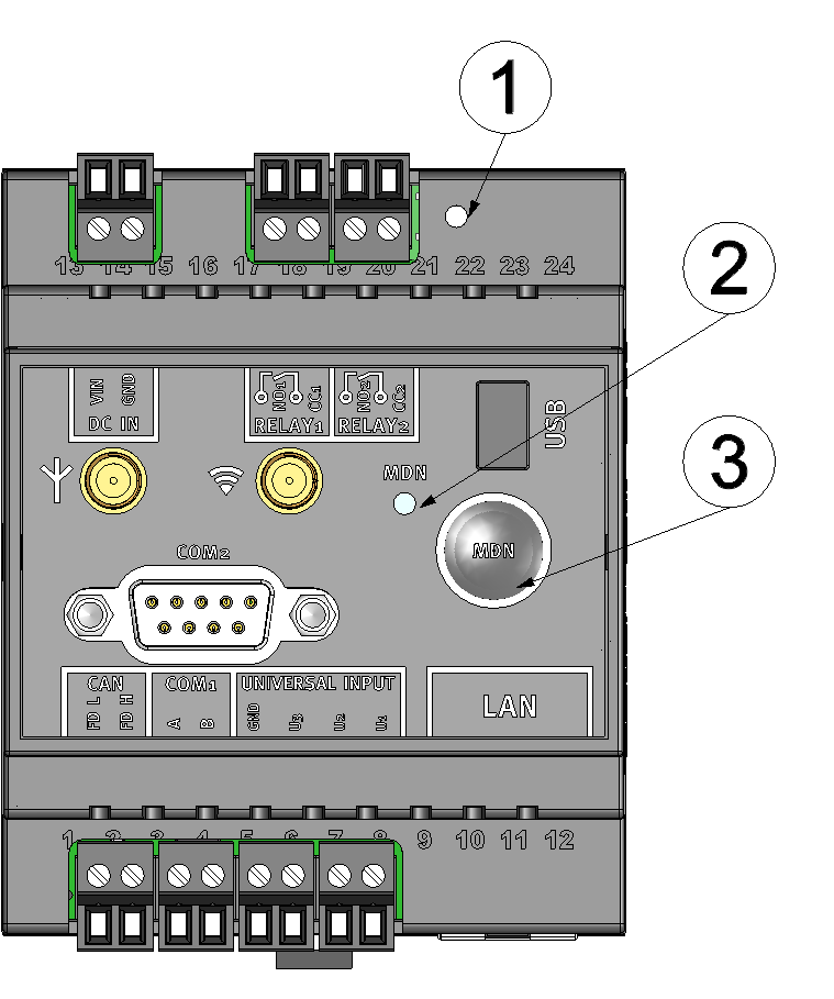
Operating elements
| 1 | Reset button | 3 | Button to trigger another connection establishment or a complete device synchronisation |
| 2 | Status LED |
The status LED is used both to display the error/status codes and to indicate the current operating state. The error/status codes are issued every 3 seconds unless there is an active mobile network connection.I.e. the output of error and status codes does not need to be enabled separately.
A detailed description is provided in section Status LED.
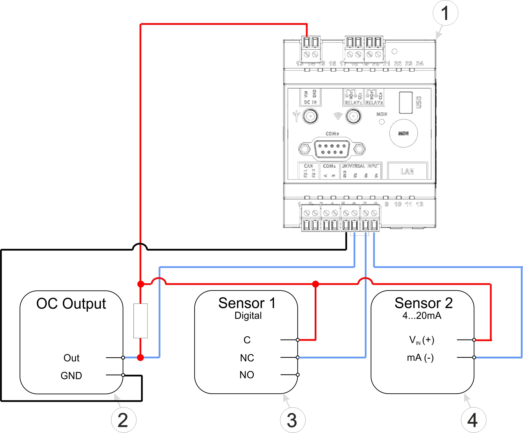
Connection examples (OC output, digital, 0/4...20 mA)
| 1 | myDataconC3 | 4 | Isolated relay contact |
| 2 | Sensor with open collector output | 5 | 2-wire mA sensor |
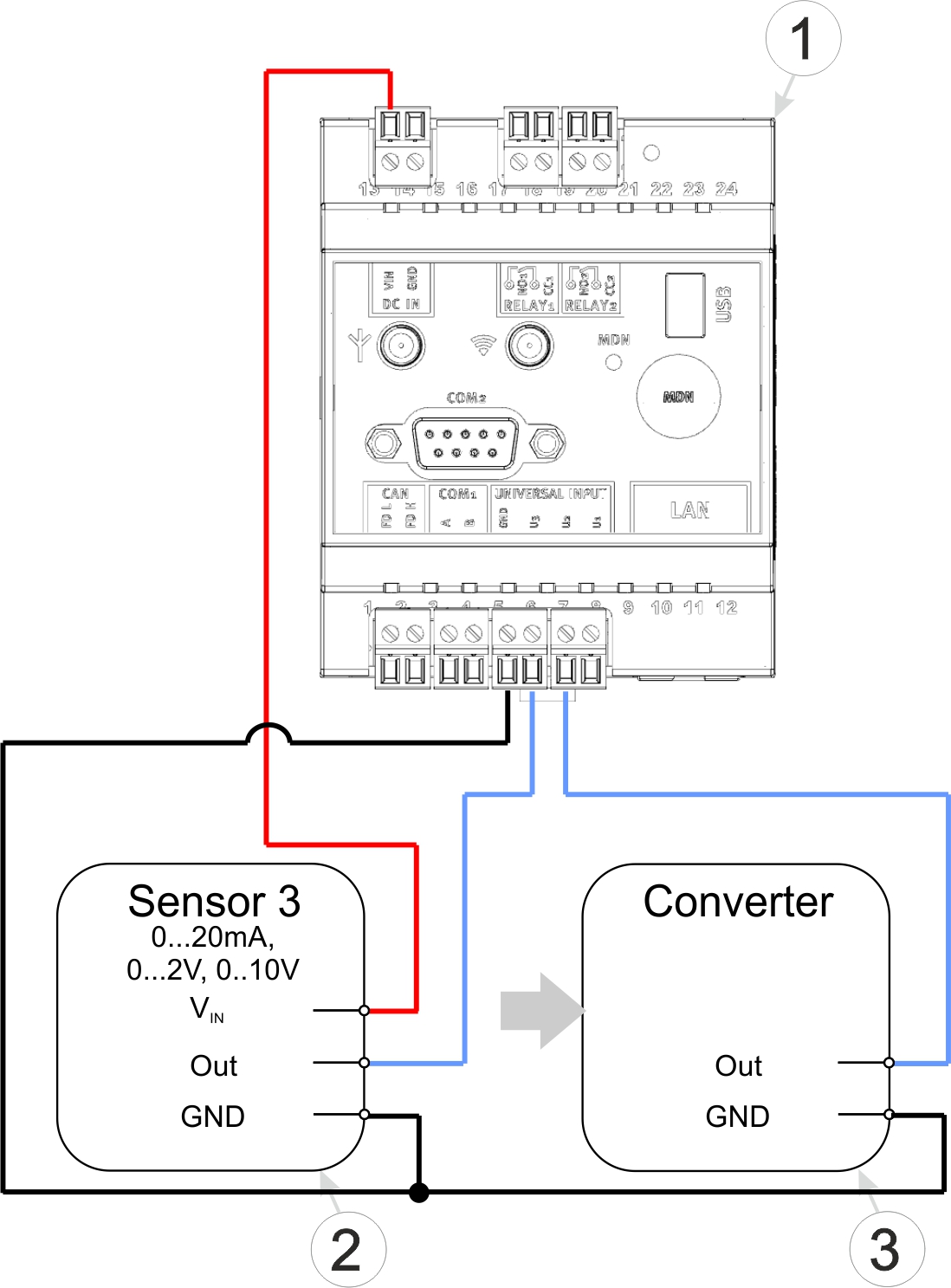
Connection examples (0...20 mA, 0...2 V, 0...10 V, converter)
| 1 | myDataconC3 | 2 | Signal converter, isolating transducer |
| 3 | 3-wire mA sensor or 3-wire U-sensor |
A detailed explanation is provided in section Connection of the sensors, actuators and the supply.
The myDataconC3 does not have a special transport mode and therefore does not need to be deactivated.
A more detailed explanation is provided in section Storage of the product.
No.
The currently available variants of the myDataconC3 are not equipped with a WiFi module. The port for the WiFi antenna is intended for future upgrades.
No.
The CAN interface is intended solely for connecting extension modules. However, these are not supported by the myDataconC3 . Extension modules can only be used with the myDataconC3+ .
No.
The RS485 interface is not supported by themyDataconC3 . The RS485interface can only be used with the myDataconC3 MBM .
No.
In the currently available variants of the myDataconC3 , the necessary hardware is no longer installed. The visible LAN socket could only be used with the "myDatalogC33x WIFI/2G/3G/4G World", which is, however, no longer available.


