Internal channels
Configuration section to configure the settings for the internal channels (e.g. mobile network field strength). The designation of the individual channels can be determined via the "Basic" tab. The "Alarms" tab is used to enter the alarm thresholds and the via the "Trigger" tab the trigger thresholds and the actions to be performed if the trigger conditions are met are determined.
Basic

"Internal channels" configuration section, "Basic" tab
| 1 | freely selectable channel designation for:
|
||
| 2 | String that is used as measurement unit from all display elements of the server |
Alarms
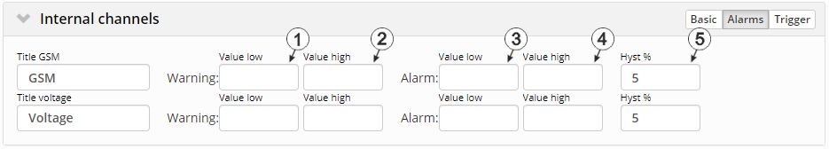
"Internal channels " configuration section, "Alarms" tab
| 1 | A warning is triggered, if the measurement value drops to or below this value. |
| 2 | A warning is triggered, if the measurement value meets or exceeds this value. |
| 3 | An alarm is triggered, if the measurement value drops to or below this value. |
| 4 | An alarm is triggered, if the measurement value meets or exceeds this value. |
| 5 | Hysteresis for all-clear in event of alarm/warning (e.g. Hyst=5 %, alarm or warning at 100 -> all-clear at 95) |
Trigger
The following two type of triggers are differentiated:
- Event trigger (RI, XM)
The relevant operation (e.g. record immediately) is only executed once when the trigger event occurs.
- Level trigger (ON, RA, D1, D2, QX)
The relevant operation (e.g. use alternative redord interval) is executed as long as the trigger is active.
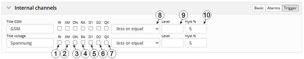
"Internal channels" configuration section, "Trigger" tab
| Event trigger: | ||
| 1 | Execute recording immediately | |
| 2 | Initiate transmission | |
| Level trigger: | ||
| 3 | Activate online mode | |
| 4 | The alternative record interval should be used. | |
| 5 | If this checkbox has been selected, the setpoint on the output channel "RELAY1" of the data logger is controlled using trigger. In doing so, the setpoint entered via the interface is ignored. The normal state of the output channel is "off (low)" and switches to "on (high)" if trigger is active. However, if "Invert" is active for the output channel, the behaviour described above is reversed. See Example explaining how to determine the switching state at the output via trigger. | |
| 6 | If this checkbox has been selected, the setpoint on the output channel "RELAY2" of the data logger is controlled using the trigger. In doing so, the setpoint entered via the interface is ignored. The normal state of the output channel is "off (low)" and switches to "on (high)" if trigger is active. However, if "Invert" is active, the behaviour described above is reversed. | |
| 7 | The alternative transmission cycle should be used. | |
| 8 | Selection if the corresponding action is to be performed upon exceeding or falling below the value entered in the "level" field | |
| greater or equal |
Event trigger: The trigger is initiated if the measurement value meets or exceeds this value. Level trigger: The trigger is active as long as the measurement value is higher than the level or equal to the level. |
|
| less or equal |
Event trigger: The trigger is initiated if the measurement value drops to or falls below this value. Level trigger: The trigger is active as long as the measurement value is lower than the level or equal to the level. |
|
| 9 | Levels for initiating the trigger. The hysteresis is used to determine the level to reset the trigger. | |
| 10 | Hysteresis for revoking the trigger (e.g. hyst=5 %, level = greater or equal, trigger at 100 -> all-clear at 95) | |


