Calculated channels
In the "Basic" tab, the basic settings are configured and in the "Calculation" tab the advanced configurations are set, whereas the parameters to configure depend on the "mode" selected in the "Basic" tab.
Basic
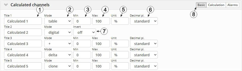
"Calculated channels" configuration section, "Basic" tab
| 1 | Freely selectable channel title for the calculated channels [0-16 characters] | |
| 2 | Possible calculation modes for the calculated channels | |
| Off | Calculated channel deactivated | |
| Table | Determines the value for the calculated channel by searching for the row corresponding to the value of a measurement channel in the reference point table. Such a row is made up of the "Measurement channel value" and "Output value for calculated channel" pair of values. Linear interpolation is carried out between the table rows; linear extrapolation is used for values outside the defined table. | |
| Digital | Converts an analogue value into a digital value. The threshold from which an analogue value is interpreted as "high" can be selected via the "High level" parameter in the "Calculation" tab. In addition the determined digital value can be inverted via the "Invert" parameter. | |
| +, -, x, / | Links the values of two measurement channels using a mathematic operation (addition, subtraction, multiplication or division) | |
| Delta | Determines the difference between two measurement values and divides the result by the time difference between the time stamps of the measurement values. The time unit (value/sec., value/min., ...) for the result can be selected via the "Time basis" parameter located in the "Calculation" tab. It is thus possible to convert counter readings (m3) of the source into a flow rate (m3/min.) (see Additional explanation: Delta mode). | |
| clone | Creates a clone of a measurement channel. This ensures it is possible to rename channels, to select different ends of the scale for the pointer instruments, to determine a new string as a measurement unit and to adjust the number of decimal places. The measurement values (numerical value without unit) correspond exactly to those of the source. | |
| 3 | Defines the lower scale end of the pointer instruments | |
| 4 | Defines the upper scale end of the pointer instruments in reports | |
| 5 | String that is used as a measurement unit by all of the server display elements [0-16 characters]. It has no direct influence on the values | |
| 6 | Number of decimal places that are used by all of the server display elements | |
| 7 | Inverts the input signal (only for calculated channels in "Digital" mode) | |
| 8 | Buttons to switch between the individual tabs of the configuration section | |
Calculation

"Calculated channels" configuration section, "Calculation" tab
| 1 | Selection of the channel from which the input data is used |
| 2 | Opens the screen for entering the reference point table (the table rows are interpolated linearly, values outside of the defined table are extrapolated linearly.) |
| 1 | Selection of the channel from which the input data is used |
| 3 | Signal recognition level |
| 1 | Selection of the channel from which the input data is used |
| 4 | Selection of the second channel from which the input data is used |
| 6 | Offset that is added following multiplication with the "Factor" parameter |
| 7 | Factor with which the result of the mathematical operation (+, -, x, / ) is multiplied. The "Offset" parameter is then added. |
| 1 | Selection of the channel from which the input data is used |
| 5 | Specifies the desired time unit (value/sec., value/min., ...) for the result |
| 6 | Offset that is added following multiplication with the "Factor" parameter. The result is converted in to the desired time unit before multiplication with the "Factor" parameter. |
| 7 | Factor with which the result is multiplied once it has been converted into the desired time unit. The "Offset" parameter is then added. |
| 1 | Selection of the channel from which the input data is used |
| 6 | Offset that is added following multiplication with the "Factor" parameter |
| 7 | Factor with which the value of the measurement channel to be cloned is multiplied. The "Offset" parameter is then added. |
Additional explanation: Delta mode
Assumption: The source channel contains the counter reading of an infinite counter in m3. The calculated channel 1 should contain the flow rate in m3/s and calculated channel 2 should contain the flow rate in l/h.
| Parameter | Value channel 1 | Value channel 2 |
|---|---|---|
| Basis -> mode | Delta | Delta |
| Basis -> unit | m3/s | l/h |
| Calculation -> time basis | Seconds | Hours |
| Calculation -> offset | 0 | 0 |
| Calculation -> factor | 1 | 1000 |
| Source | Calculated channel 1 | Calculated channel 2 | |
|---|---|---|---|
| Date/time | Infinite counter [m3] | Flow rate [m3/s] | Flow rate [l/h] |
| 26.03.2013 12:50 | 900 | 0 1) | 0 1) |
| 26.03.2013 12:51 | 960 | 1 | 3,600,000 |
| 26.03.2013 12:52 | 990 | 0.5 | 1,800,000 |
| 26.03.2013 12:53 | 1005 | 0.25 | 900,000 |
| 26.03.2013 12:54 | 1065 | 1 | 3,600,000 |
1)Calculation not possible as there is no measurement value before 12:50.
Explanation: No values can be determined for the measurement at 12:50 for the calculated channels as there is no previous value and the difference between the counter readings cannot be determined. For the measurement at 12:51, the difference to the counter reading is 60 m3 and the time difference is 60 sec.
Result = { (value difference / time difference [sec.]) * time basis [sec] * factor } + offset
The result for calculated channel 1 (time basis "Seconds", offset "0" and factor "1") is calculated as follows:
Channel 1 = { (60 m3 / 60 sec.) * 1 * 1 } + 0 = 1 m3/s
The result for calculated channel 2 (time basis "Hours", offset "0" and factor "1000") is calculated as follows:
Channel 2 = { (60 m3 / 60 sec.) * 3600 * 1000 } + 0 = 3,600,000 l/h
Alarms
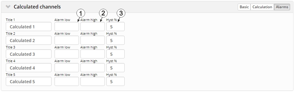
"Calculated channels" configuration section, "Alarms" tab
| 1 | An alarm is triggered, if the measurement value drops to or below this value. |
| 2 | An alarm is triggered, if the measurement value meets or exceeds this value. |
| 3 | Hysteresis for all-clear in event of alarm/warning (e.g. Hyst = 5 %, alarm at 100 -> all-clear at 95) |


