Technical details about the CAN interface
The components of the myDataconC3+ (i.e. data logger and extensions) are connected via CAN bus (see Connection of the extension modules). No other bus participants should be connected with this CAN bus (i.e. a separate, encapsulated CAN bus is required). The CAN interfaces of the components have no galvanic separation between the CAN bus and the CAN controller. However, the output drivers of the CAN interface are protected against overloading and are not damaged by a short circuit. For components located at the end of the CAN bus, the 120 Ω resistance integrated in the device must be activated via S3 and S4 of the dip switch. Neither of the two resistances are active in the delivered condition. The dip switch to activate/deactivate the load resistances is located on the rear of the myDataconC3+ .
| S1 and S2 | 2k load resistance between CAN high and CAN low |
| S3 and S4 | 120Ω load resistance between CAN high and CAN low |
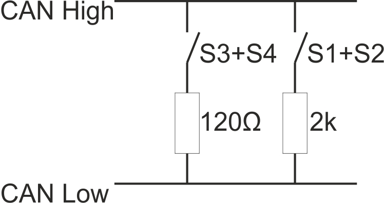
Schematic diagram of the switchable load resistances
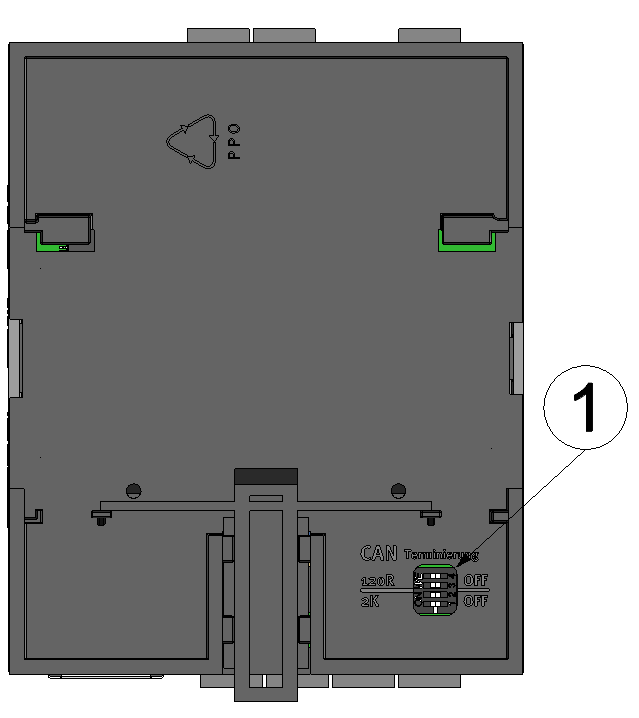
Position of the dip switches
| 1 | Dip switch for activating/deactivating the load resistances for the CAN interface |


