Fixed mounts
For the installation of the VEL‑R‑5 , fixed mounts are available for various installation situations (see Assembly sets). The alignment of the VEL‑R‑5 with the flume to be measured is carried out for all fixed mounts using the procedure described below.
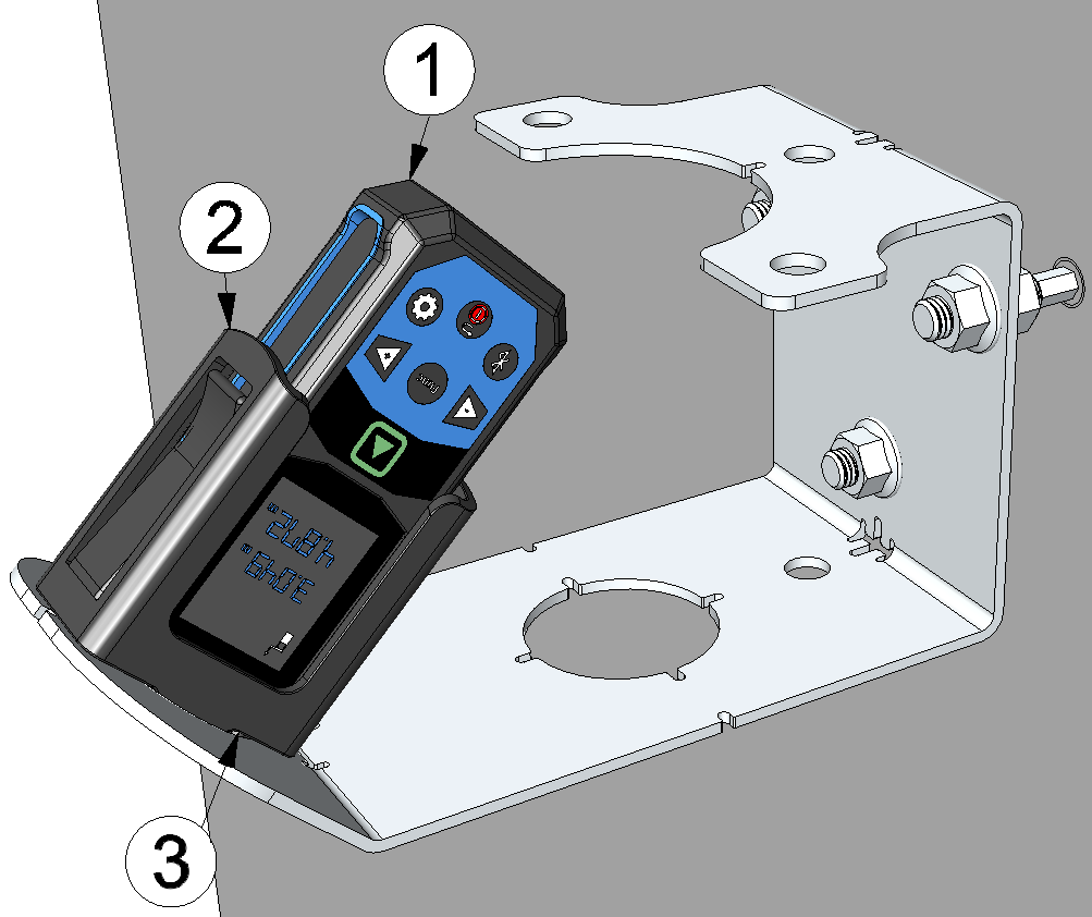
Aligning the VEL‑R‑5 using a laser distance meter
| 1 | Laser meter Bosch GLM50-27CG 301757 |
| 2 | Laser meter adapter Bosch PRO GLM 50-xxx " (301756, optional accessory) |
| 3 | Flow velocity sensor holder |
- First, install the sensor bracket that is suitable for your installation situation. You will find further information in the chapters Wall/ceiling mounting (fixed mount) and Mounting on the ceiling of the sewer.
- Activate the distance measurement (distance symbol) on the laser distance meter and
insert it into the optional accessory "Laser meter adapter Bosch PRO GLM 50-xxx
" (301756). Then position
the Laser meter adapter Bosch PRO GLM 50-xxx
in the holder for the flow velocity sensor.
Note: The display of the laser distance meter must be positioned perpendicular to the axis along which the flow velocity sensor holder is tilted.The following laser distance meters are compatible with the adapter:
- Bosch PRO GLM 50-27 CG
- Bosch PRO GLM 50-27 C
- Bosch PRO GLM 50-25 G
- Bosch PRO GLM 50-23 G
- Bosch PRO GLM 50-22
- Bosch PRO GLM 40-31
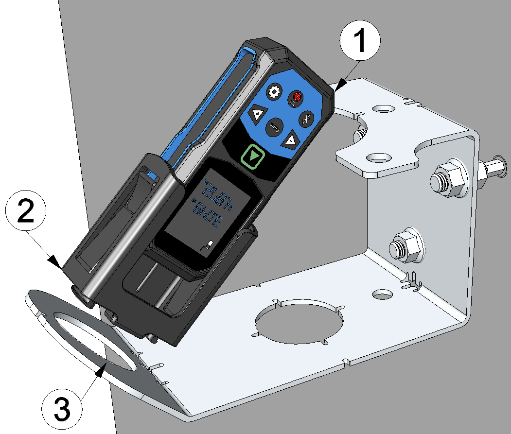
Inserting the laser distance meter into the flow velocity sensor holder
1 Laser meter Bosch GLM50-27CG 301757 2 Laser meter adapter Bosch PRO GLM 50-xxx (301756) 3 Flow velocity sensor holder - Loosen all nuts. Move the three adjustment nuts by turning them forwards or backwards
to align the sensor mount. You can use the laser beam of the laser distance meter to
determine the point at which the surface speed is measured. The use of three mounting
points allows precise adjustment of the sensor mount in all spatial directions.
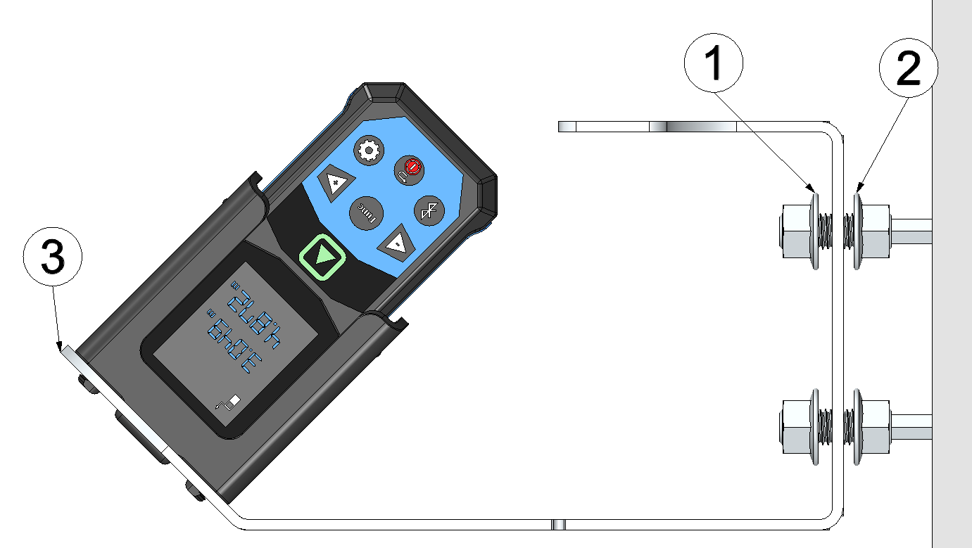
Aligning the sensor mount
1 Nut for locking in position 2 Nut for adjusting alignment 3 Sensor mount (wall/ceiling mounting) - Secure the sensor mount by tightening the three locking nuts again. Activate the angle measurement (spirit level symbol) on the laser distance meter and note the angle of attack, as this may deviate from the design-related 45° due to the inclination of the sensor mount. Secure the sensor mount by tightening the three locking nuts again. The angle of attack must later be entered in the input mask for configuring the data logger linked to the VEL‑R‑5 so that the surface velocity can be calculated correctly.
- Remove the Laser meter adapter Bosch PRO GLM 50-xxx
from
the flow velocity sensor mount. Then insert the VEL‑R‑5
into the flow velocity sensor mount and secure it using the G
1½" union nut supplied with the VEL‑R‑5
. The "top
marking" (horizontal line between the two arrows on the type plate) must be aligned
upwards and the longitudinal axis of the sensor, which is inclined at 45°, must be aligned
parallel to the flow.
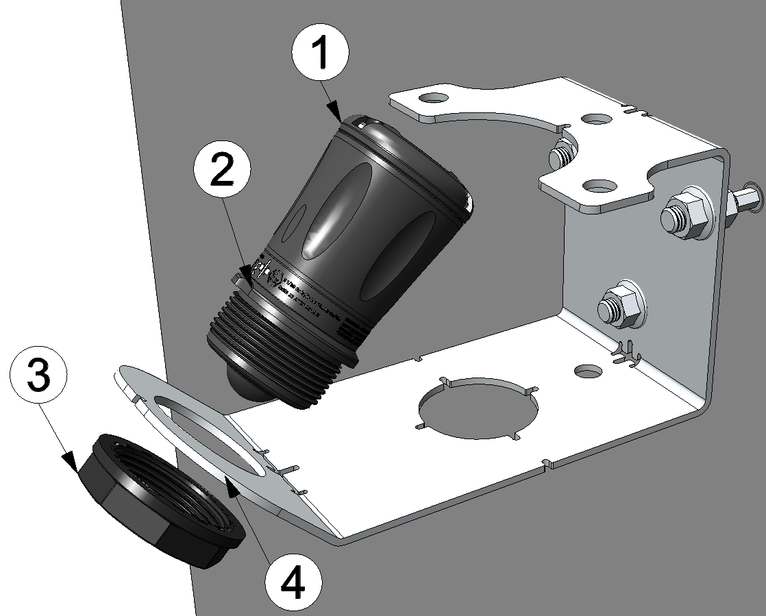
Inserting the VEL‑R‑5 into the flow velocity sensor holder
1 VEL‑R‑5 2 Top marking 3 G 1½" Überwurfmutter 4 Flow velocity sensor holder 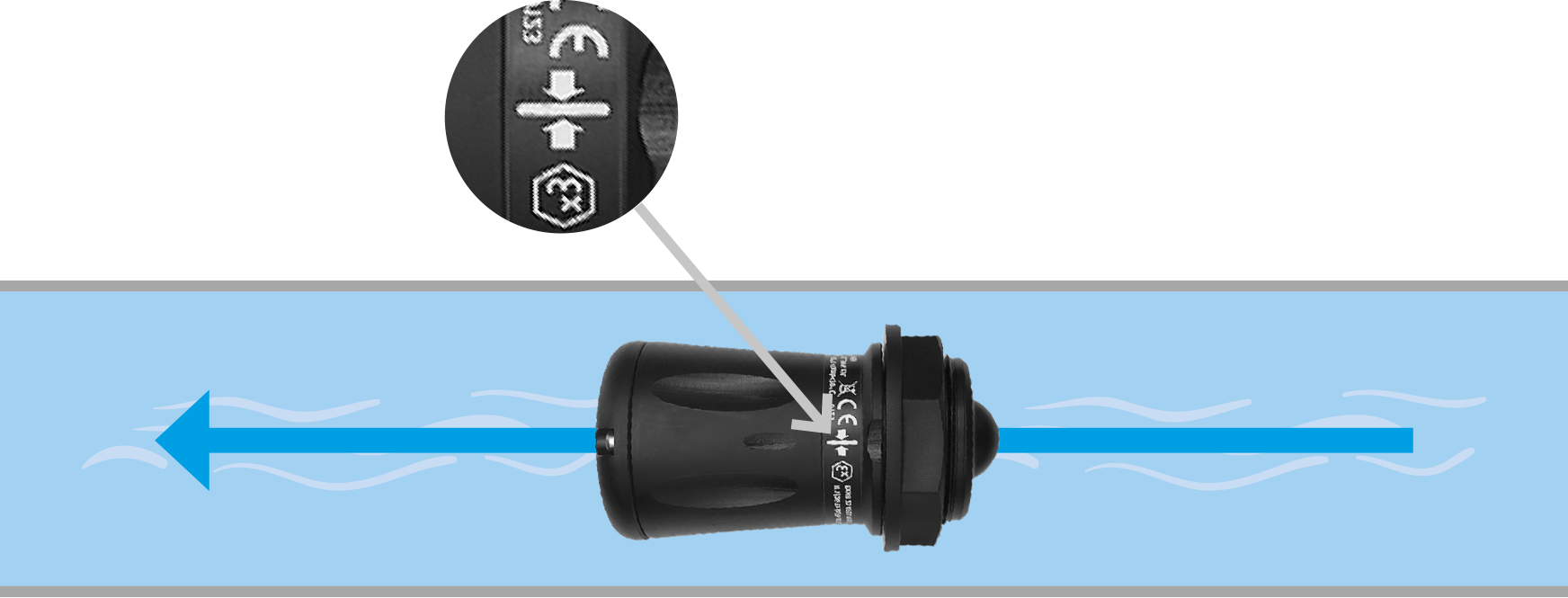
Correct alignment of the VEL‑R‑5 relative to the flow (view from above)


