Overview
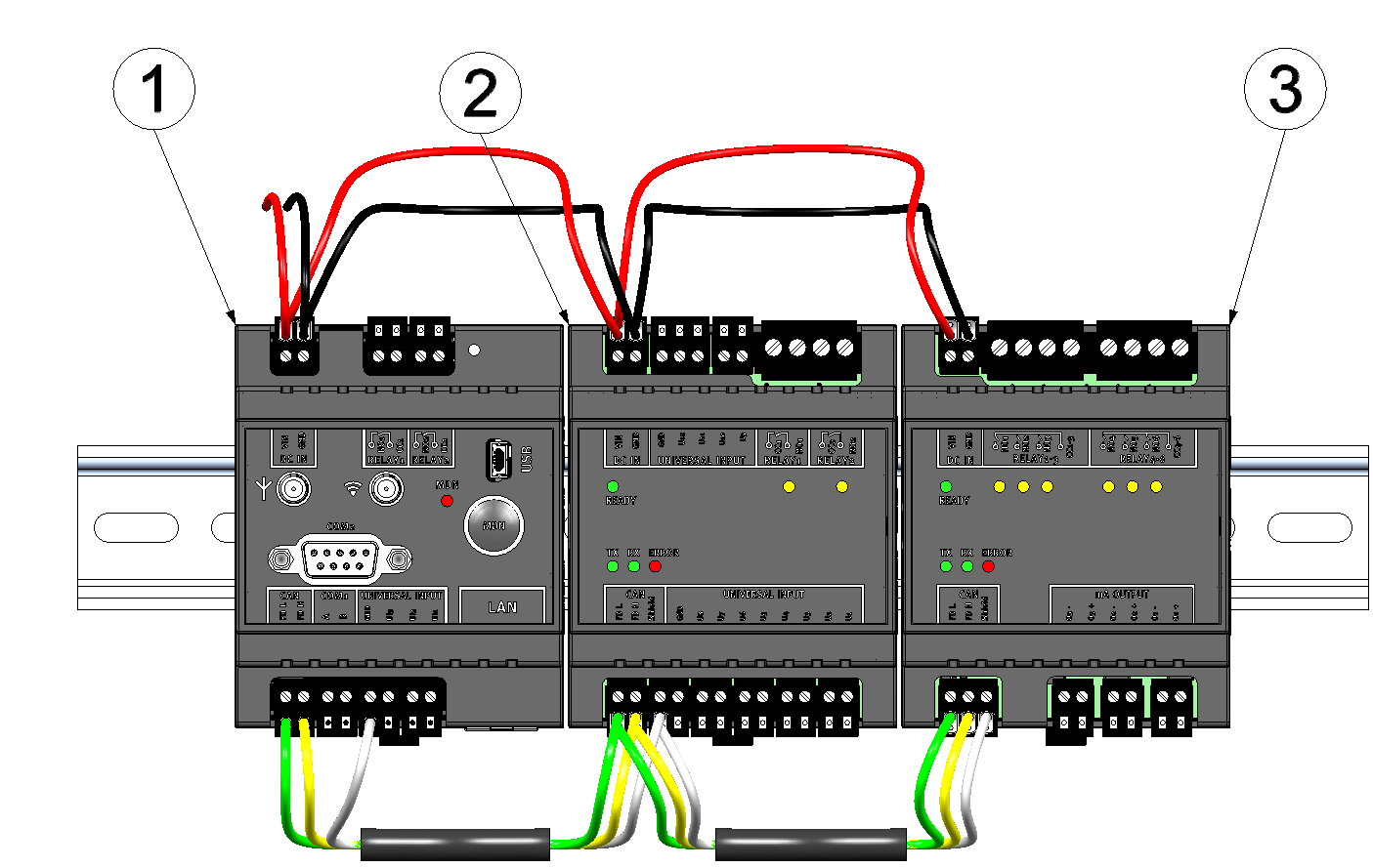
Maximum configuration of the measurment system "myDataconC3+ "
| 1 | Data logger (e.g. myDatalogC32x 2G/4G World ) |
| 2 | Input extension (myDatalogC3e 12UI/2Rel ) |
| 3 | Output extension (myDatalogC3e 3mA/6Rel ) |
Data logger
|
Front of the myDatalogC3xx |
Rear of the myDatalogC3xx |
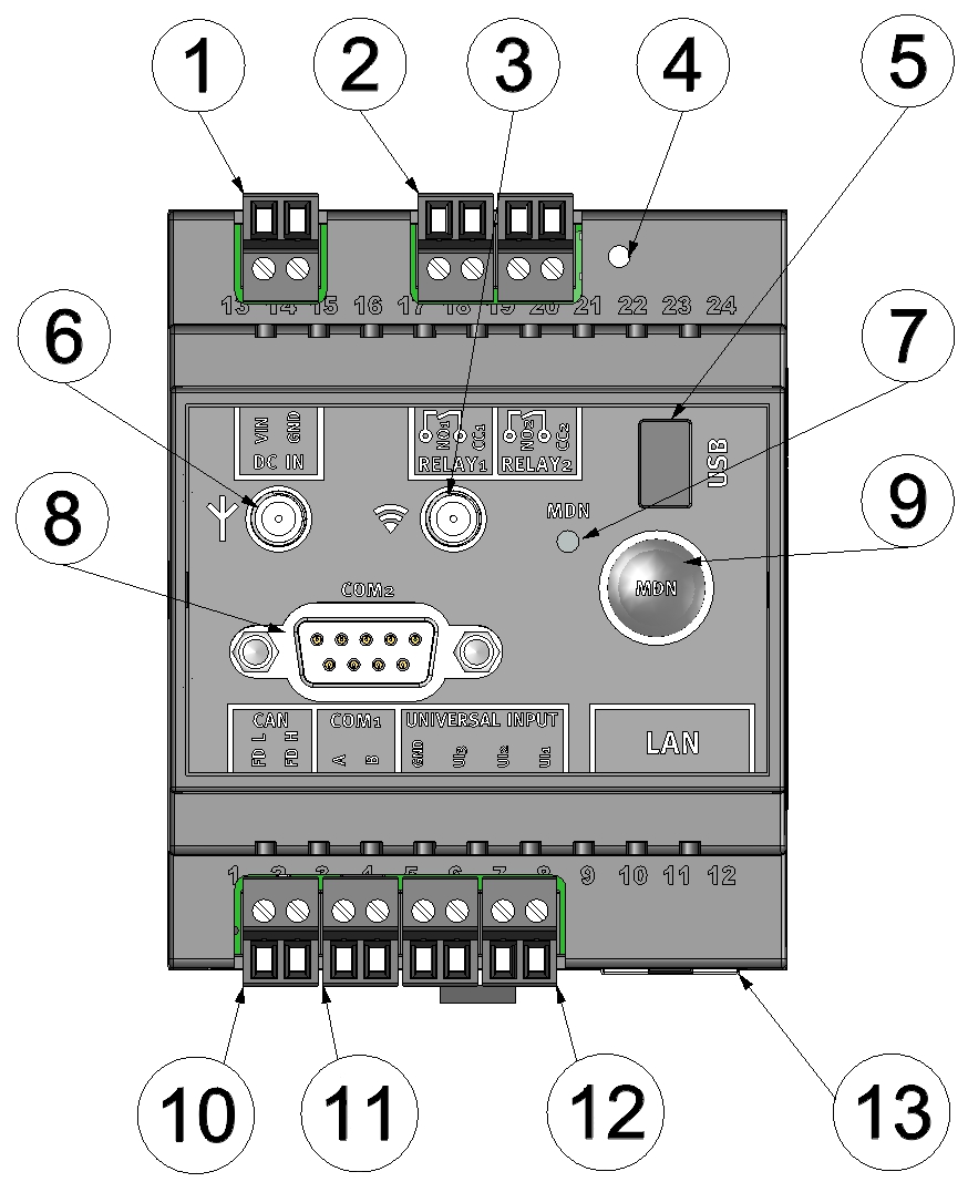
| 1 | Supply (V IN, GND) | 8 | Reserved for extensions |
| 2 | Relay 1-2 | 9 | Button to trigger another connection establishment or a complete device synchronisation |
| 3 | Reserved for extensions | 10 | CAN interface for the connection of extension modules |
| 4 | Reset button | 11 | Reserved for extension |
| 5 | Mini-B USB (only for debugging and device logic update) | 12 | Universal input 1-3 (incl. GND) |
| 6 | Connector for the mobile network antenna | 13 | Reserved for extension |
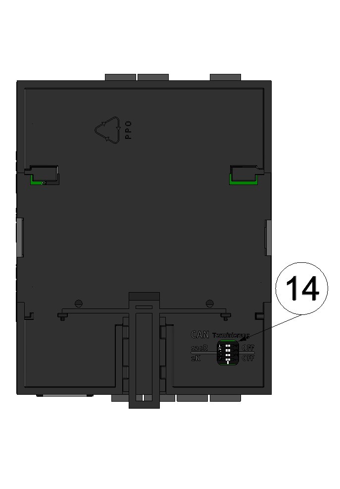
| 7 | Status LED | 14 | Dip switch for activating/deactivating the load resistances for the CAN interface |
Input extension
|
Front of the myDatalogC3e 12UI/2Rel |
Rear of the myDatalogC3e 12UI/2Rel |
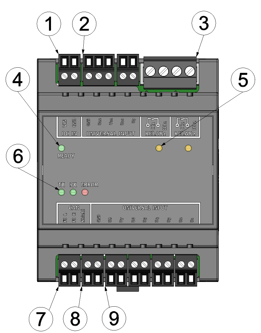
| 1 | Supply (V IN, GND) | 6 | LEDs for displaying the communication state of the CAN interface |
| 2 | Universal input 9-12 (incl. GND) | 7 | CAN interface |
| 3 | Relay 1-2 | 8 | Connections for shielding the CAN interface and GND for the universal inputs |
| 4 | LED to indicate whether the device is ready for operation | 9 | Universal input 1-8 |
| 5 | LEDs for displaying the switching states of the potential-free switching contacts | 10 | Dip switch for activating/deactivating the load resistances for the CAN interface |
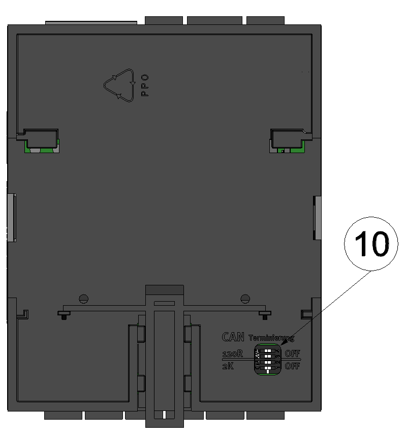
Output extension
|
Rear of the myDatalogC3e 3mA/6Rel |
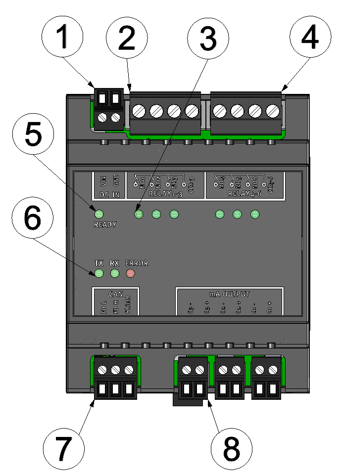
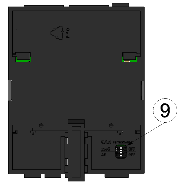
| 1 | Supply (V IN, GND) | 6 | LEDs for displaying the communication state of the CAN interface |
| 2 | Relays 1-3 (group 1 with common root) | 7 | CAN interface (inkl. Anschluss für die Schirmung) |
| 3 | LEDs for displaying the switching states of the potential-free switching contacts | 8 | Analogue outputs 1-3 (active, galvanically isolated) |
| 4 | Relays 4-6 (group 2 with common root) | 9 | Dip switch for activating/deactivating the load resistances for the CAN interface |
| 5 | LED to indicate whether the device is ready for operation |


