CAN bus without branch lines
Important: All wiring work must be performed in the de-energised state.
- Set the load resistances for the CAN interface on all of the bus participants
(extension modules and myDatalogC3xx ) based on the position they will have on the bus. The 120 Ω load resistances (S3 and S4
of the dip switch) must be activated on the first and last bus participant.
Tip: Setting the load resistances before installation of the devices is recommended as the dip switches to activate/deactivate the load resistances for the CAN interface are located on the rear of the device.
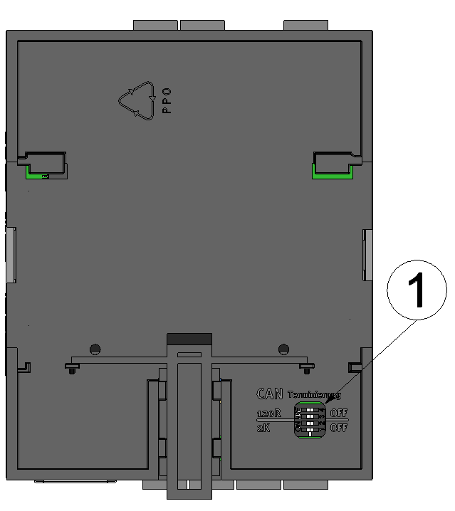
Rear of the myDatalogC3xx or of an extension module
1 Dip switch for activating/deactivating the load resistances for the CAN interface - Position the myDatalogC3xx and the extension modules in
the final installation position (e.g. next to one another on a top-hat rail). Information
regarding the correct installation of the myDataconC3+
is
provided in chapter Installing the myDataconC3+
.
Note: When selecting the installation position for the individual devices, ensure that the total length of the CAN bus20 m must not be exceeded
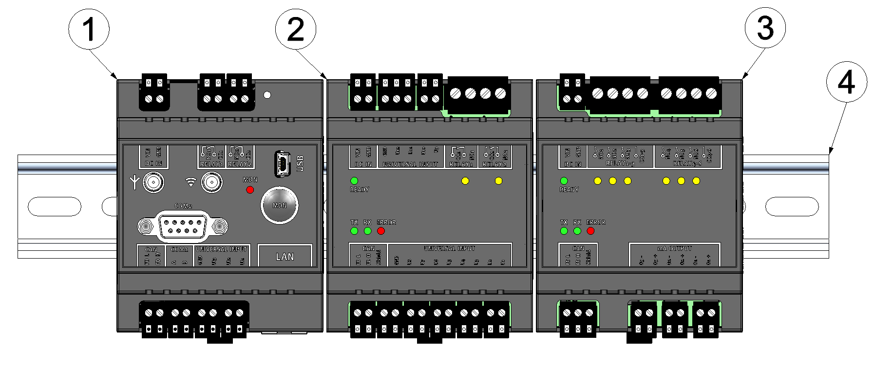
Top-hate rail with myDatalogC3xx and extension modules attached
1 myDatalogC3xx (120Ω load resistance activated) 3 myDatalogC3e 3mA/6Rel (120Ω load resistance activated) 2 myDatalogC3e 12UI/2Rel 4 Top-hat rail - Connect the CAN interface of the myDatalogC3xx with those
of the extension modules. All of the "FD L" terminals and all of the "FD
H" terminals must be connected with one another during this process. Ensure that no
current is present!
Note: Use a shielded cable to connect the CAN interfaces. The "Shield" terminal is available on the extension modules to connect the cable shield. The cable shield on the myDatalogC3xx must be connected to the GND terminal. Use a twin wire end sleeve or distributor terminal if you want to connect several cables to the GND terminal.Note: As there is only one terminal for each signal on themyDatalogC3xx and on the extension modules, you should use twin wire end sleeves if you want to use more than one extension module.
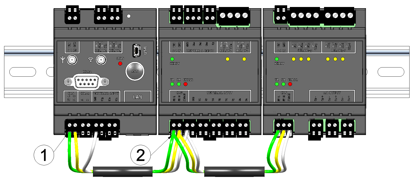
Connecting the cables of the CAN interface
1 Wire end sleeve 2 Twin wire end sleeve (wire end sleeve for two cables) - Connect your sensors and actuators with the inputs and outputs of the myDatalogC3xx and the extension module. Ensure that no current is present!
- Connect the cables for the power supply of the myDatalogC3xx and the extension modules with the VIN and GND
terminals. Ensure that no current is present when establishing the connection. In this
case, use twin wire end sleeves if more than one cable should be connected per
terminal.
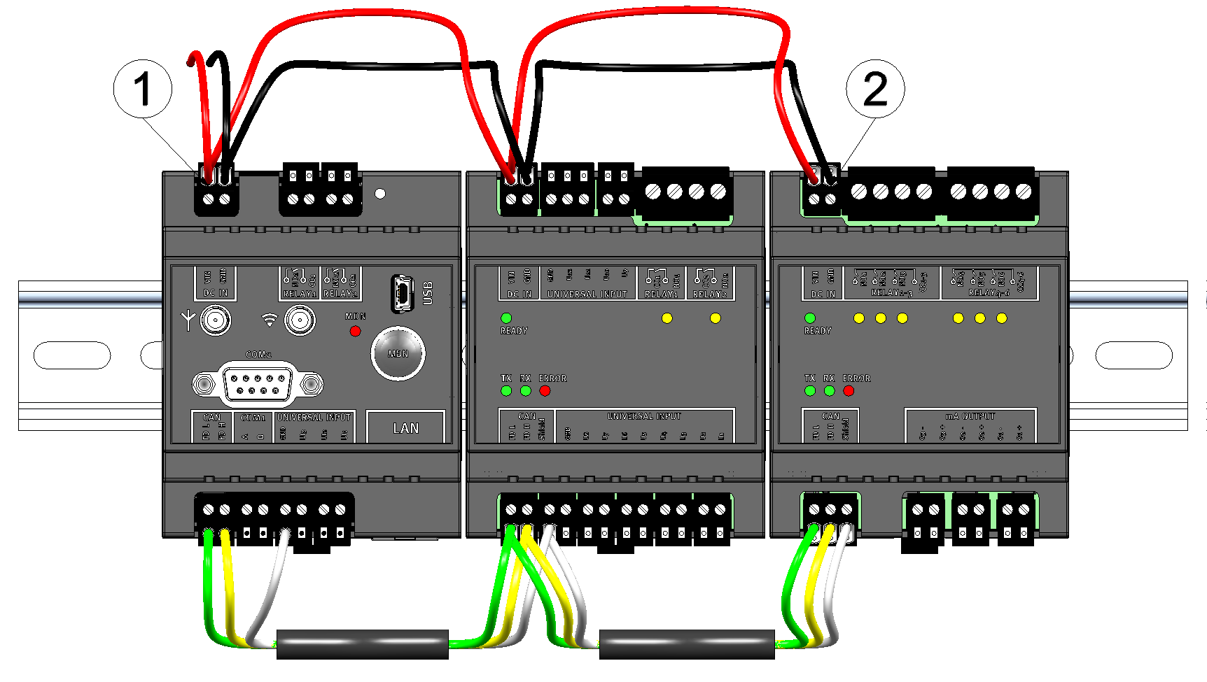
Connecting the power supply
1 Twin wire end sleeve 2 Wire end sleeve


