Flexibly adjustable mounts
For the installation of the LVL-R-5 , flexibly adjustable mounts are available for various installation situations (see Assembly sets). The alignment of the LVL-R-5 with the flume to be measured is carried out for all flexibly adjustable mounts using the procedure described below.

Aligning the LVL-R-5
| 1 | Spirit level |
| 2 | LVL-R-5 |
| 3 | Sensor recess |
| 4 | Laser meter Bosch GLM50-27CG (301757) |
| 5 | Laser meter adapter Bosch PRO GLM 50-xxx (301756, optional accessory) |
- In the first instance, install the sensor recess suitable for your installation situation. An explanation of this is provided in the chapters Wall mounting (flexibly adjustable mount), Pipe mounting, Strut/rod mounting und Installation in a manhole cover DN600.
- Roughly align the swivel arm of the sensor recess with the flume to be determined. If necessary, unlock the corresponding clamping screw.
- Insert the LVL-R-5 in the sensor recess of the mount
and fasten it using the G
1½" union nut included in the scope of supply of the LVL-R-5 .
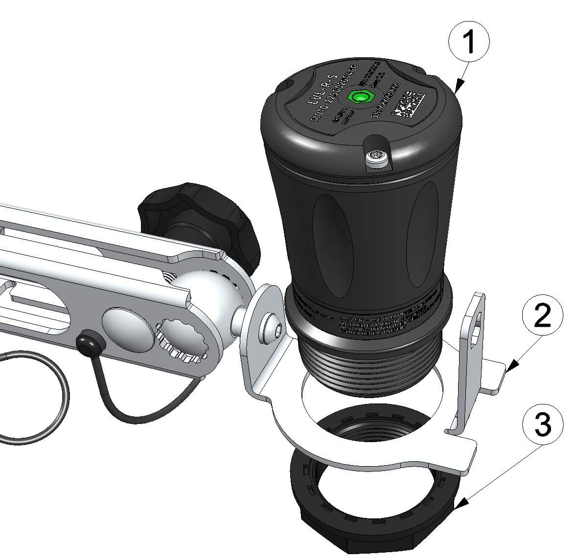
Inserting the LVL-R-5 in the sensor recess
1 LVL-R-5 2 Sensor recess 3 G 1½" union nut - Slide the optional accessory "Laser meter adapter Bosch PRO GLM 50-xxx
" (301756) on the intended
bracket of the sensor recess, then insert the already activated laser distance meter in
the adapter.
The following laser distance meters are compatible with the adapter:- Bosch PRO GLM 50-27 CG
- Bosch PRO GLM 50-27 C
- Bosch PRO GLM 50-25 G
- Bosch PRO GLM 50-23 G
- Bosch PRO GLM 50-22
- Bosch PRO GLM 40-31
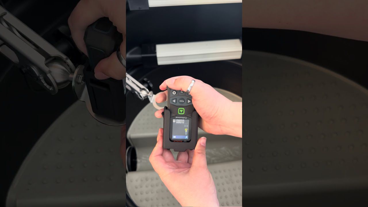
How-To-Video: Mounting the laser distance meter 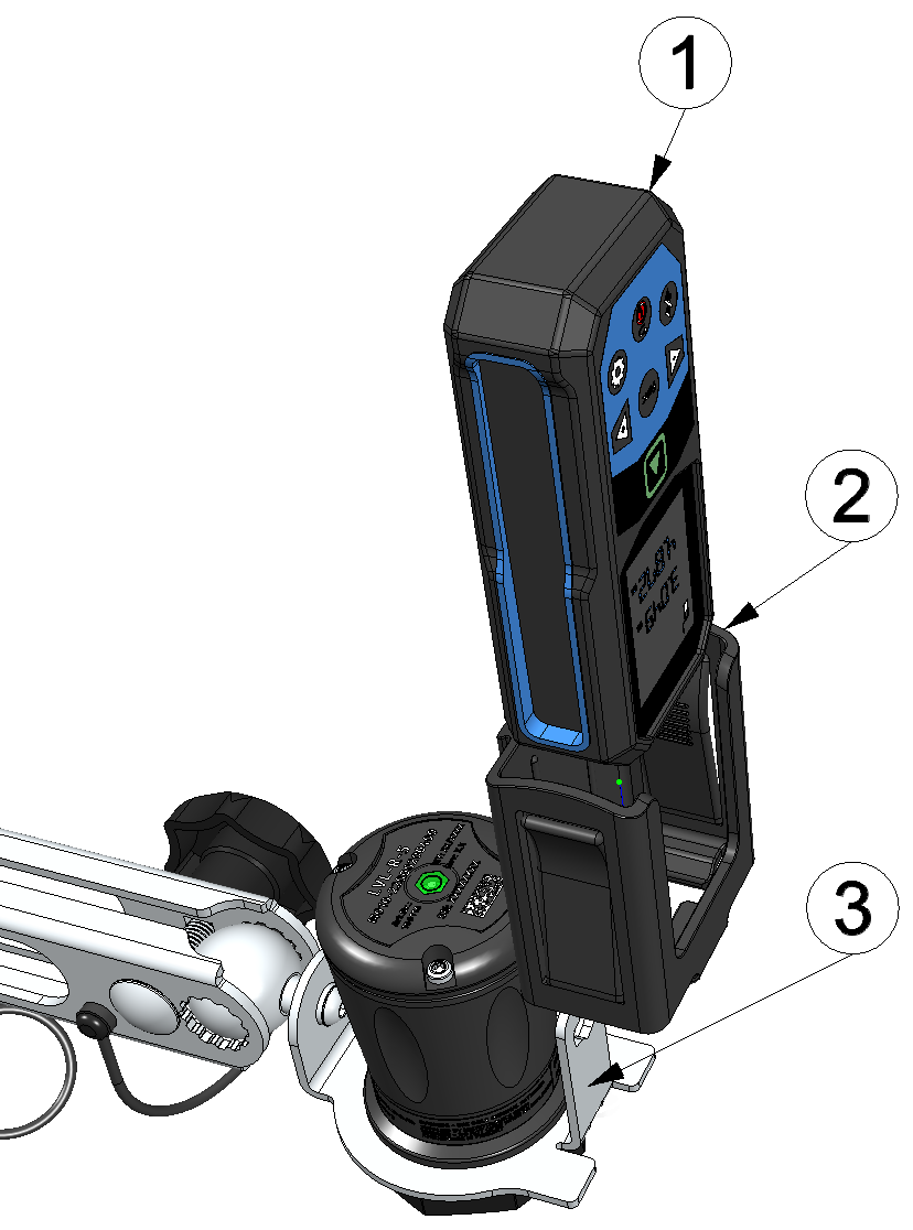
Mounting the laser distance meter
1 Laser meter Bosch GLM50-27CG (301757) 2 Laser meter adapter Bosch PRO GLM 50-xxx " (301756) 3 Bracket of the sensor recess - Loosen the clamping screw to unlock the spherical joint. Subsequently align the LVL-R-5 by means of the aid of the laser beam of the
distance meter with the spot of the flume where the water level should be determined and
use the spirit level of the LVL-R-5 to align the LVL-R-5 exactly perpendicular.
Note: Without the optional laser distance meter, the spirit level of the LVL-R-5 is the only available mounting aid for the correct alignment of the LVL-R-5 .
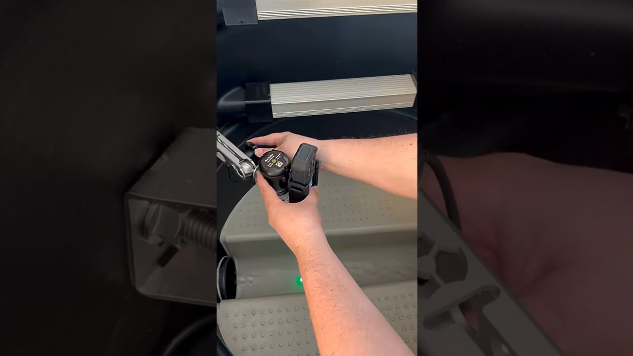
How-To-Video: Aligning the radar sensor using a laser distance meter 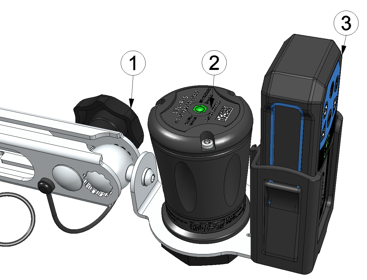
Aligning the LVL-R-5
1 Clamping screw to unlock the spherical joint 2 Spirit level 3 Laser meter Bosch GLM50-27CG (301757) - Fasten the spehrical joint again by tightening the clamping screw.
- Loosen the G
1½" union nut and remove the LVL-R-5 from the sensor
recess. Then, instead of the LVL-R-5 , install the "Laser meter adapter Bosch PRO GLM 50-xxx
" with the laser
distance meter inserted in the sensor recess and check whether the laser beam of the
distance meter points to the spot of the flume where you would like to determine the water
level.
Note: In doing so, ensure that the alignment (spehrical joint and swivel arm) of the sensor recess is not altered, provided no readjustment is needed.
Carry out an alignment correction if the laser beam does not aim for the desired spot. However, in this case you also have to recheck the perpendicular alignment in the next step.
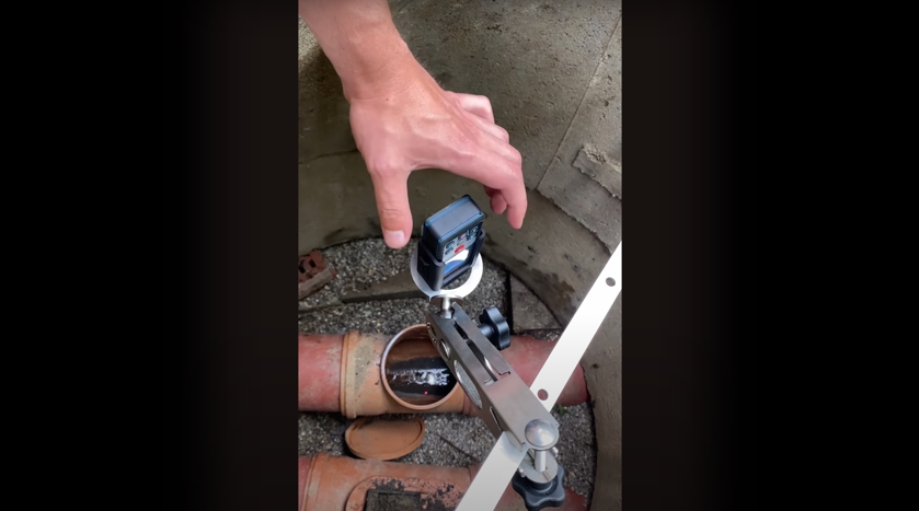
How-To-Video: Practical use of the laser distance meter 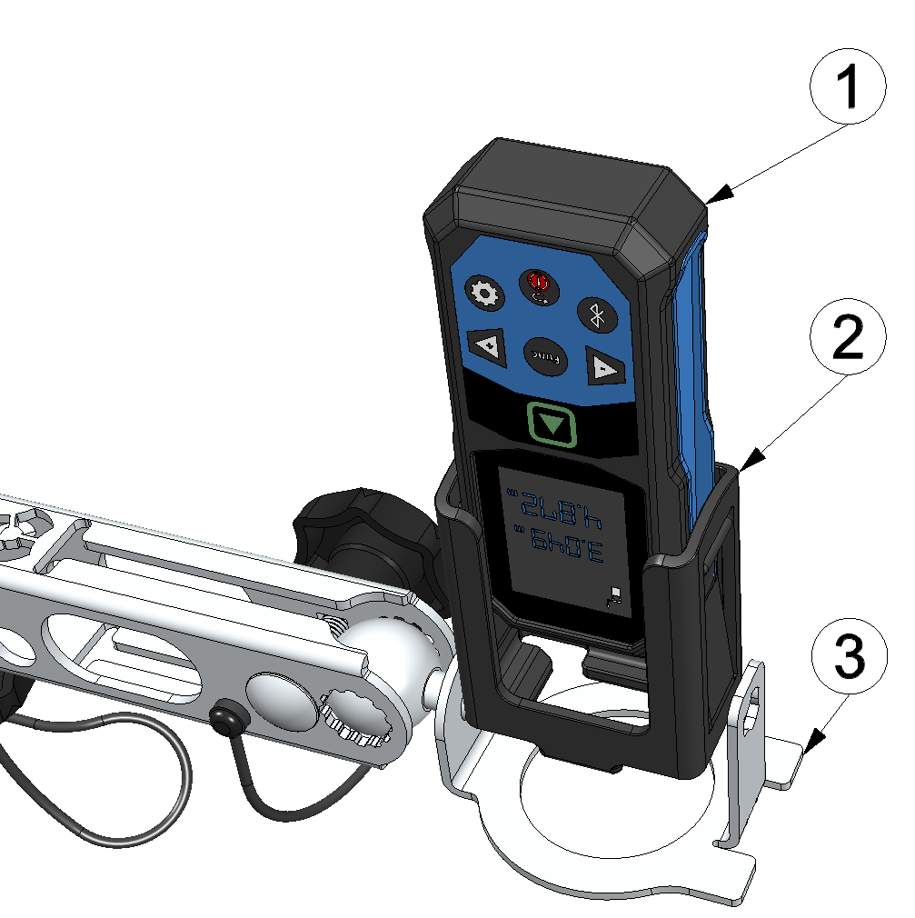
Inserting the laser distance meter in the sensor recess
1 Laser meter Bosch GLM50-27CG (301757) 2 Laser meter adapter Bosch PRO GLM 50-xxx " (301756) 3 Bracket of the sensor recess - Replace the "Laser meter adapter Bosch PRO GLM 50-xxx
"
with inserted laser distance meter again with the LVL-R-5 .
Note: In doing so, ensure that the alignment (spehrical joint and swivel arm) of the sensor recess is not altered, provided no readjustment is needed.
If the alignment of the sensor recess has been altered in the previous step, the LVL-R-5 has to be aligned exactly perpendicular again using the spirit level. Then repeat the previous step and this step until the alignment of the LVL-R-5 meets your requirements.


