Technical details about the sensor supply
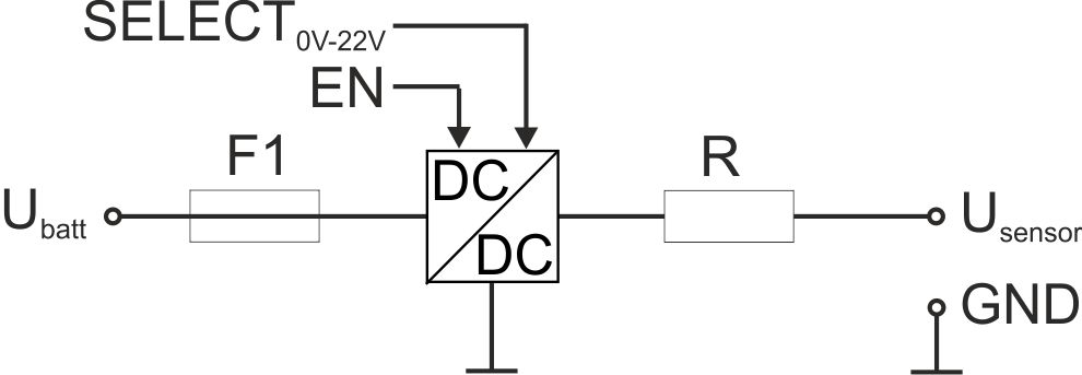
Schematic diagram of the sensor supply
| Ubatt | internal supply voltage |
| F | electronic fuse |
| R | 330 Ω |
| USensor | 0...22 V |
| Uo | 25,6 V | |
| Io | 82 mA | |
| Po | 0,523 W | |
| Lo [µH] | Co [µF] | |
| 1000 | 0,31 | |
| 250 | 0,36 | |
| 100 | 0,465 | |
The sensor supply is activated by setting a value for the warmup time in the input window "Universal input" (see Universal input). The warmup time specifies how long before the measurement the sensor supply is switched on. If it is set to 0sec., the sensor supply will neither be activated prior to nor during the measurement.
| Basic settings |  | Measurement cycle | 1min. |
| Measurement channel -> configuration |  | Warmup time | 20sec. |
| Output at the device |  | Sensor supply |
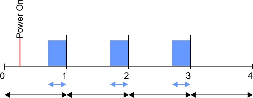
Explanation: The sensor supply is activated 20sec prior to the measurement interval each time, meaning that the value provided at the time of measurement is valid.
| Basic settings |

|
Record interval | 5min. |
|
|
Measurement cycle | 1min. | |
| Measurement channel -> configuration |
|
Ext. warmup time | 1sec. |

|
Filter time | 500ms | |
| Output at the device |
|
Sensor supply |
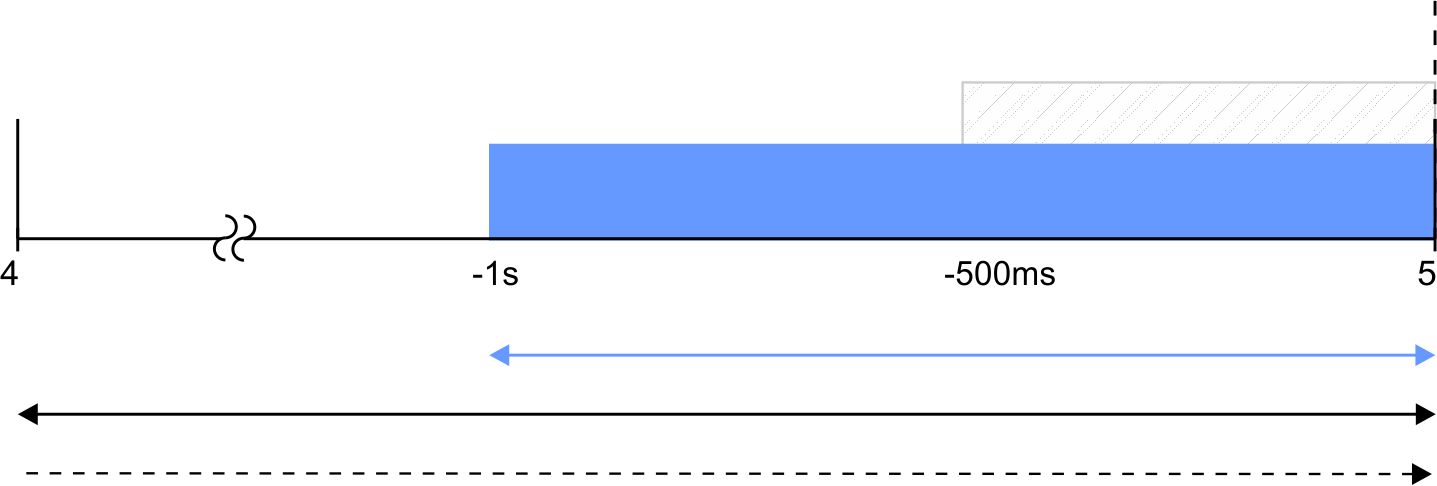
Explanation: The sensor supply is always activated 1sec before expiry of the measurement cycle. The filter time starts 500ms before expiry of the measurement cycle, which ensures that a valid value is available at the time of a measurement. However, this also means that the filter time must be taken into consideration when selecting the Ext. warmup time. In the current example, the sensor connected to the input must at the latest supply stable values 500ms following activation of the sensor supply. Otherwise, invalid values would be taken into consideration while averaging during the filter time resulting in the measurement value being distorted.


