Display
- Do not touch the display with sharp objects, such as the tip of a pen.
- Do not stand or place any objects on the display as this could scratch it.
General
The display of the Jellox Analog is only designed to show the current measurement values and various status information. The device cannot be operated via the display. The display is activated by briefly holding the magnet (approx. 1 sec.) to the reed switch (see Reed switch). The display then remains active for 20 sec. , showing first the boot screen for 1 sec. (see Boot screen) and then consecutively the tabs with information about the Jellox Analog itself, the mA input and the sensor modules.Using the solenoid switch you can disable automatic switching between the tabs and switch manually between the display screens (see Reed switch). The "detected hold of the reed switch" symbol is displayed in the status bar for as long as the MDN Magnet (206.803) is held to the corresponding position on the Jellox Analog (see Operating elements).
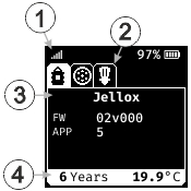
General structure of the display
| 1 | Status bar | 3 | Information about the current tab |
| 2 | Display of the available tabs with specific information | 4 | Footer of the current tab |
The tab on which information is currently shown on the display is highlighted by a white background. The background of the other tabs is black, provided no error has occurred with the respective components (Jellox Analog , mA input or sensor module) of which they contain the information. The fact that one of the tabs not currently displayed contains an error code can be recognised by the red background. If the display is switched to a tab that contains an error code, the colour of the icon in the tab changes from white to black. A list of possible error codes is provided in chapter Error codes.
|
Tab with valid information |
Jellox tab with error code |
Sensor module tab with error code |
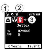
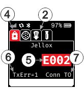

| 1 | Current tab with valid informationen | 5 | Error code (see Error codes) |
| 2 | Inactive tab with valid informationen | 6 | TxError code (only applies to error code E002) |
| 3 | Inactive tab with error code | 7 | Brief description of TxError code or EMM Reject Cause (only applies to error code E002) |
| 4 | Current tab with error code |
Boot screen
The boot screen is shown for 1 sec. after activating the display by briefly actuating (approx. 1 sec.) the reed switch (see Reed switch).

Boot screen
Status bar
The status bar is located at the top border of the display and shows information about the network connection, mobile network connection, radio connection and the state of charge.
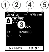
Sections of the status bar
| 1 | Information about the nework connection | |

|
field strength of the mobile network signal during the last connection | |

|
transport mode activated | |
| 2 | Status of the mobile network connection | |

|
mobile connection disconnected; wait for next connection establishment | |

(blinking) |
connecting | |
|
|
connection to the myDatanet server established | |

|
last connection failed | |
| 3 | Status of the local radio connection | |

|
establishing local radio connection to the sensor modules | |
| 4 | Status of the reed switch | |

|
reed switch not actuated | |

|
detected hold of the reed switch | |
| 5 | current state of charge of the battery of the Jellox Analog . To the left, the state of charge (SOC) is displayed in % | |

|
State of Charge >= 90 % | |

|
State of Charge >= 40 % | |

|
State of Charge >= 10 % | |

|
State of Charge < 9 % | |
Information about the Jellox Analog
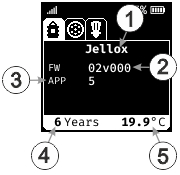
Display of the information on the Jellox Analog
| 1 | Brief designation of the IoT application installed on the device | 4 | remaining time until the next battery replacement of the Jellox Analog |
| 2 | Current software version installed on the measurement controller | 5 | Temperature inside the housing of the device |
| 3 | Version number of the IoT application that is currently installed on the device |
Information about the mA input
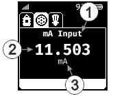
Display of the information on the mA input
| 1 | indicates that the information on the mA input is currently displayed | 3 | Unit of the measurement value set via the server interface |
| 2 | measurement value on the mA input (scaled measurement value with offset and trimming taken into consideration) |
Information about the remote sensor modules
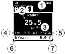
Display of the information on a sensor module type "LVL‑R‑5 "
| 1 | Indicates sensor category (e.g. velocity sensor) of the sensor module for which the information is displayed | 5 | Serial number of the sensor module |
| 2 | Current level1) | 6 | Remaining time until the next battery replacement of the sensor module |
| 3 | Unit of length (mm, cm or m) selected via the server interface | 7 | Temperature of the electronics of the sensor module |
| 4 | Product designation of the sensor module (as indicated on the type plate) |
1) If the firmware of the sensor module is being updated, the message "Update" is displayed instead of the level.
Error codes
| Error code | Description | ||||||||||||||||||||||||||||||||||||||||||||||||||||||||||||||||||||||||
|---|---|---|---|---|---|---|---|---|---|---|---|---|---|---|---|---|---|---|---|---|---|---|---|---|---|---|---|---|---|---|---|---|---|---|---|---|---|---|---|---|---|---|---|---|---|---|---|---|---|---|---|---|---|---|---|---|---|---|---|---|---|---|---|---|---|---|---|---|---|---|---|---|---|
| E001 | sensor configuration not permitted for this variant | ||||||||||||||||||||||||||||||||||||||||||||||||||||||||||||||||||||||||
| E002 | last mobile network connection failed The following table contains a breakdown of the TxError codes that explain the cause of the failure in more detail. If the mobile network returns an EMM Reject Cause, the display shows the EMM Reject Cause instead of the brief description.
|
||||||||||||||||||||||||||||||||||||||||||||||||||||||||||||||||||||||||
| E003 | radio connection to remote sensor/actuator not possible | ||||||||||||||||||||||||||||||||||||||||||||||||||||||||||||||||||||||||
| E013 | unambiguous selection of the sensor for the measurement channel not possible | ||||||||||||||||||||||||||||||||||||||||||||||||||||||||||||||||||||||||
| E014 | state of charge of the internal rechargeable buffer battery too low for a mobile network connection to be established (recharging automatically may take up to 4 hours) | ||||||||||||||||||||||||||||||||||||||||||||||||||||||||||||||||||||||||
| E020 | no valid measurement value | ||||||||||||||||||||||||||||||||||||||||||||||||||||||||||||||||||||||||
| E100 | hardware error (contact the manufacturer) | ||||||||||||||||||||||||||||||||||||||||||||||||||||||||||||||||||||||||
| E110 | analogue input faulty (contact the manufacturer) | ||||||||||||||||||||||||||||||||||||||||||||||||||||||||||||||||||||||||
| E120 | sensor cable between Gauge and pressure sensor damaged | ||||||||||||||||||||||||||||||||||||||||||||||||||||||||||||||||||||||||
| E140 | setpoint output not possible as the current loop is interrupted |


