Universal input
Basic settings
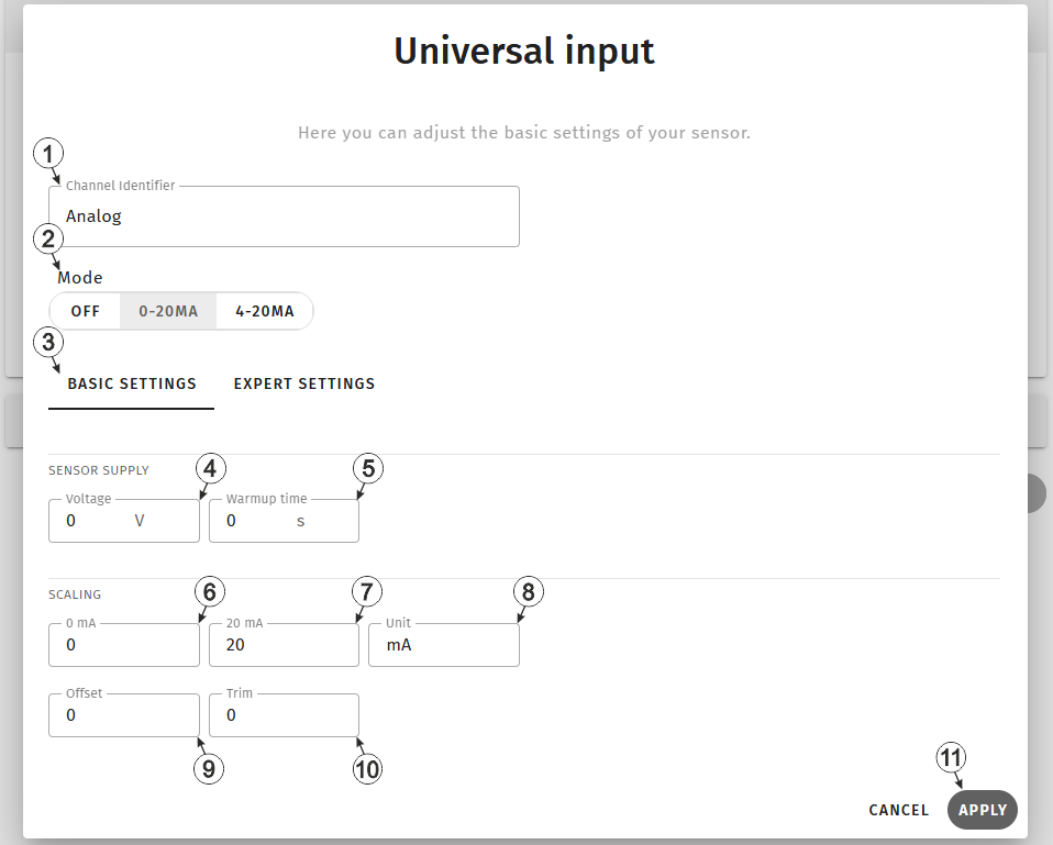
Input window "Universal input", tab "Basic settings"
| 1 | Freely selectable,
variable part of the designation for the measurement values determined via the mA
input on the Jellox Analog . Several measurement values are recorded using the mA input. Their name is made up of the variable part and a fixed part ("myName - Value", "myName - Vsens", "myName - Warmup Time", etc.). |
|
| 2 | Buttons for selecting
the mode for the measurement channel Tip: When selecting the mode, the values for "Start of the measurement range in the measurement unit" and "End of the measurement range in the measurement unit" are
automatically set to 0 mA | 20 mA (mode 0-20 mA) or 4 mA |
20 mA (mode 4-20 mA). During commissioning, the current signal
supplied by the sensor is displayed directly. The values can of course be
overwritten manually. |
|
| Off | Measurement channel deactivated | |
| 0-20 mA | Valid input signal range 0...20 mA (0 mA = 0 %, 20 mA = 100 %) | |
| 4-20 mA | Valid input signal range 4...20 mA (4 mA = 0 %, 20 mA = 100 %) | |
| 3 | Buttons for switching between the individual tabs of the input window | |
| 4 | Selection of the output voltage for the sensor supply | |
| 5 | specifies the time (in 0,1 sec.) for which the sensor supply is switched on before the measurement (see Technical details about the sensor supply) | |
| 6 | Start of the measurement range in the measurement unit | |
| 7 | End of the measurement range in the measurement unit | |
| 8 | String that is used as a measurement unit by all of the server display elements [0‑8 characters] | |
| 9 | Allows for correction of the measurement value by an offset value (see Additional explanation on the zero point adjustment and installation height of the sensor) | |
| 10 | Is
used to adjust the zero point (see Additional explanation on the zero point adjustment and installation height of the sensor) Tip: Additional explanations on the zero point adjustment (i.e. taking
triming into account) can be found in the user manual of the relevant sensor
module. |
|
| 11 | Button to apply the settings
Note: To save the settings, the "Save" button below the "Smart Actions" configuration
section must also be clicked.
|
|
Additional explanation on the zero point adjustment and installation height of the sensor
Assumption: Measurement range of the 4-20 mA pressure sensor 0-5 m
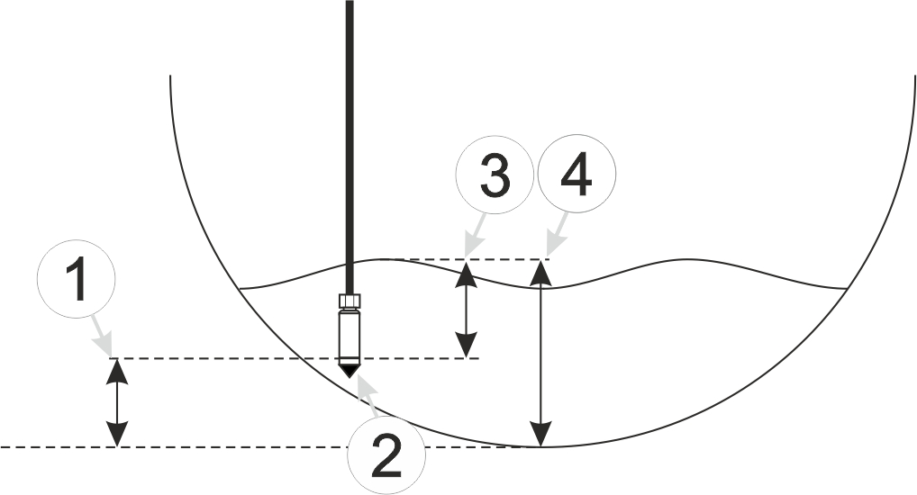
Installation situation of the pressure sensor
| 1 | Installation height: 15 cm | 3 | Output value of the sensor: 6 cm |
| 2 | Pressure sensor | 4 | Measured fill level: 20 cm |
| Parameter | Value |
|---|---|
| Mode | 4-20 mA |
| 0 % | 0 |
| 100 % | 5 |
| Trim | -0.01 |
| Offset | 0.15 |
| Unit | m |
Explanation: When comparing the measured fill level with the output value of the sensor taking the installation height into consideration, it was determined that the value was 1 cm too high. As the "Trim" and "Offset" parameters are added to the scaled measurement value, this error can be balanced out by setting the "Trim" parameter value to -0.01 m.
Expert settings
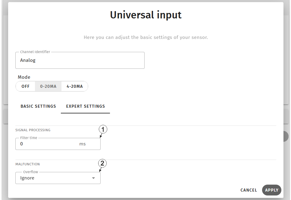
Input window "Universal input", tab "Expert settings"
| 1 | Time in [ms], during which the analogue signal is averaged for signal smoothing, is designed to suppress signal noise (see "Example to explain the filter time in conjunction with the Ext. warmup time" in chapter Technical details about the sensor supply) | |
| 2 | Procedure in the event of measurement range violations | |
| Ignore | The measurement value is calculated beyond the range limits. | |
| Silent cutoff | The measurement value is truncated at the range limits. | |
| NAMUR |
0...20 mA mode:
4...20 mA mode:
|
|


