Online help for 4-Channel Data Logger MBM
General product information
The 4-Channel
Data Logger MBM is a data logger designed for stand-alone operation.
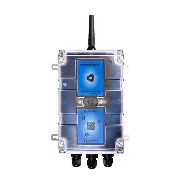
Product characteristics:
- Modbus client
- Modbus via RS485 interface
- Operating mode Modbus/RTU
- galvanically separated RS485 interface (order option)
- Universal inputs for digital and analogue signals
- Switchable and adjustable supply voltage for sensors
- Isolated switch contact
- Internal battery compartment
- Battery, rechargeable battery or direct power supply
- Exactstate of charge of the battery using Coulombmethod
- Space for additional components in the housing
- Integrated charge control
- Configurable via web interface
- Device time synchronised with the sever
- Hardware real-time clock
- Very low commissioning & operating costs
- Integrated durable SIM chip
Application:
- Data exchange with Modbus server
- Level measurement
- Flow measurement
- Temperature measurement
- Transmission of measurement values of probes
- Remote meter reading
This online help is applicable from:
Frequently asked questions (FAQs)
| Blink code | Colour | Description |
|---|---|---|
| 0x | --- | Transport lock (transmission OFF, measurement OFF) |
| 1x | green | Last connection OK |
| 2x | red | Last transmission faulty |
| 7x | red | Network block/no matching provider |
| 8x | red | No mobile network |
| 9x | red | incorrect PIN/1 attempt remaining |
| 10x | red | No mobile network connection |
| 11x | red | No server available |
| 12x | red | Faulty SIM chip |
A detailed explanation is provided in section Three colour status LED.
Yes.
The combi antenna "Flat antenna Disc multi band 2xFME-F 2m " (301196), which contains two mobile network antennas, is recommended in such cases. Alternatively, 2 separate antennas of the same type can also be used.
A list of available antennas is provided in section Antennas.
|
| How-To-Video: Triggering Aloha transmission mode |
Tap theMDN Magnet (206.803) for at least 3 sec. on the position shown in the following figure.
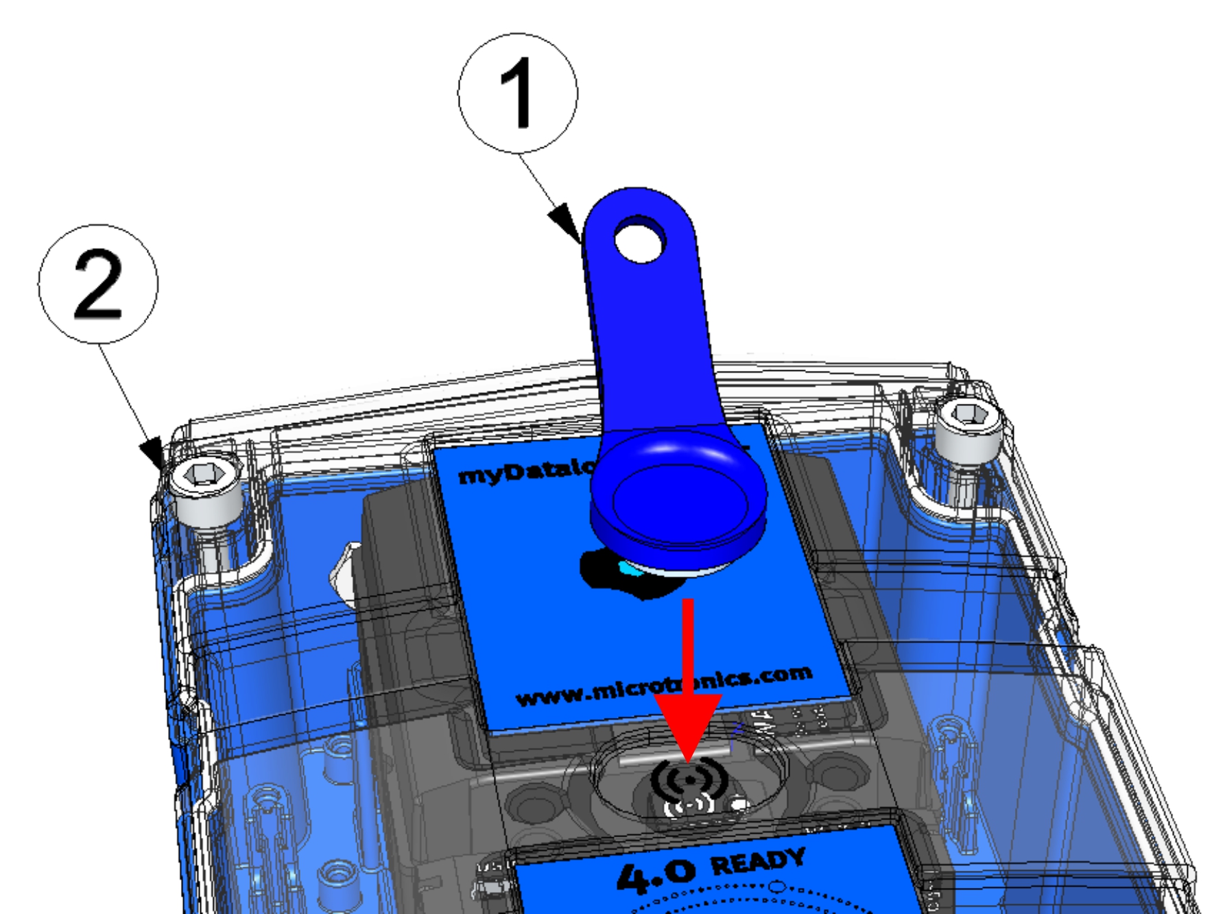
| 1 | MDN Magnet (206.803) | 2 | 4-Channel Data Logger MBM |
Briefly (approx. 1 sec.) tap theMDN Magnet (206.803) on the position shown in the following figure.
Use a shielded twisted pair cable to prevent electromagnetic interference caused by the environment. The total length of the cables connecting the Modbus servers must not exceed 30 m. It is advisable to use a multi-core cable in which data and power lines can be routed together. When connecting multiple Modbus servers, only a bus structure is permitted. Stubs or star and tree topologies are not permitted.
A detailed explanation is provided in section Connecting the sensors, actuators and power supply.
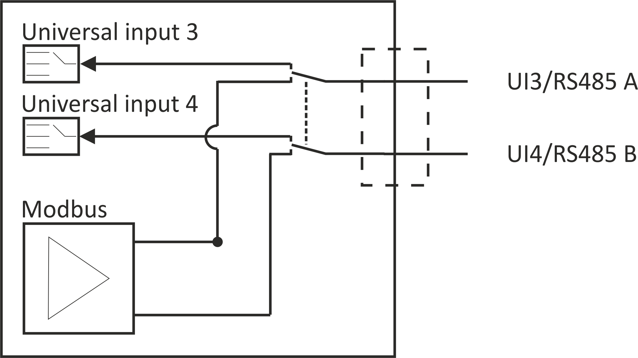
The RS485 interface is used for communication with Modbus servers. RS485 A and universal input 3 share a terminal on the main terminal strip. The same applies to RS485 B and universal input 4. Therefore, universal inputs 3 and 4 are not available when using Modbus.
Further information is provided in section Connecting the sensors, actuators and power supply
When using the OnBoard RS485 interface:
Via the checkbox "Termination" located in the input mask for configuring the modbus interface, the 120Ω termination resistance between RS485 A and B can be switched on. (see Modbus interface)
The onBoard RS485 interface has no clamp resistances (pull up to RS485 A and pull down to RS485 B).
A detailed explanation is provided in section Technical details about the onBoard RS485 interface.
When using the optional RS485 interface extension :
In contrast to the onBoard RS485 interface, the 120Ω terminal resistance cannot be activated via the interface of the myDatanet server but must instead be activated via the 4-pin dip switch on the interface card. The clamp resistances can also be activated via this dip switch. The following table indicates the required settings for the switches.
| S1 | S2 | S3 | S4 | |
|---|---|---|---|---|
| Off | Off | Off | Off | Neither terminal nor clamp resistance active |
| Off | Off | Off | On | 120Ω terminal resistance or RS485 A and RS485 B |
| On | On | Off | Off | 390Ω clamp resistances active |
| On | On | On | Off | 140Ω terminal resistaces and 390Ω clamp resistances active Default settings upon delivery |
A detailed explanation is provided in section RS485 interface extension.
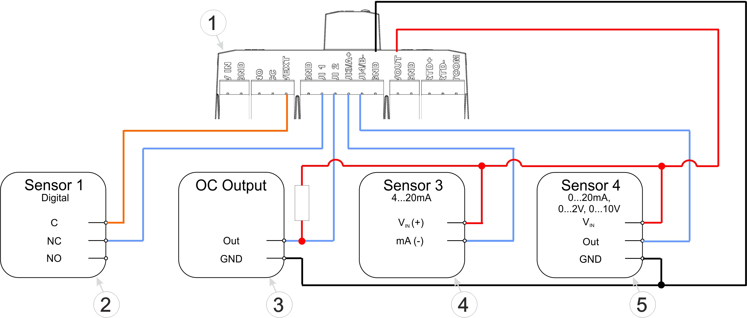
Connection examples (digital, open collector output, 0/4...20 mA, 0...2/10 V)
| 1 | Main terminal block of the 4-Channel Data Logger MBM | 4 | 2-wire mA sensor |
| 2 | Isolated relay contact | 5 | 3-wire mA sensor or 3-wire U-sensor |
| 3 | Sensor with open collector output |
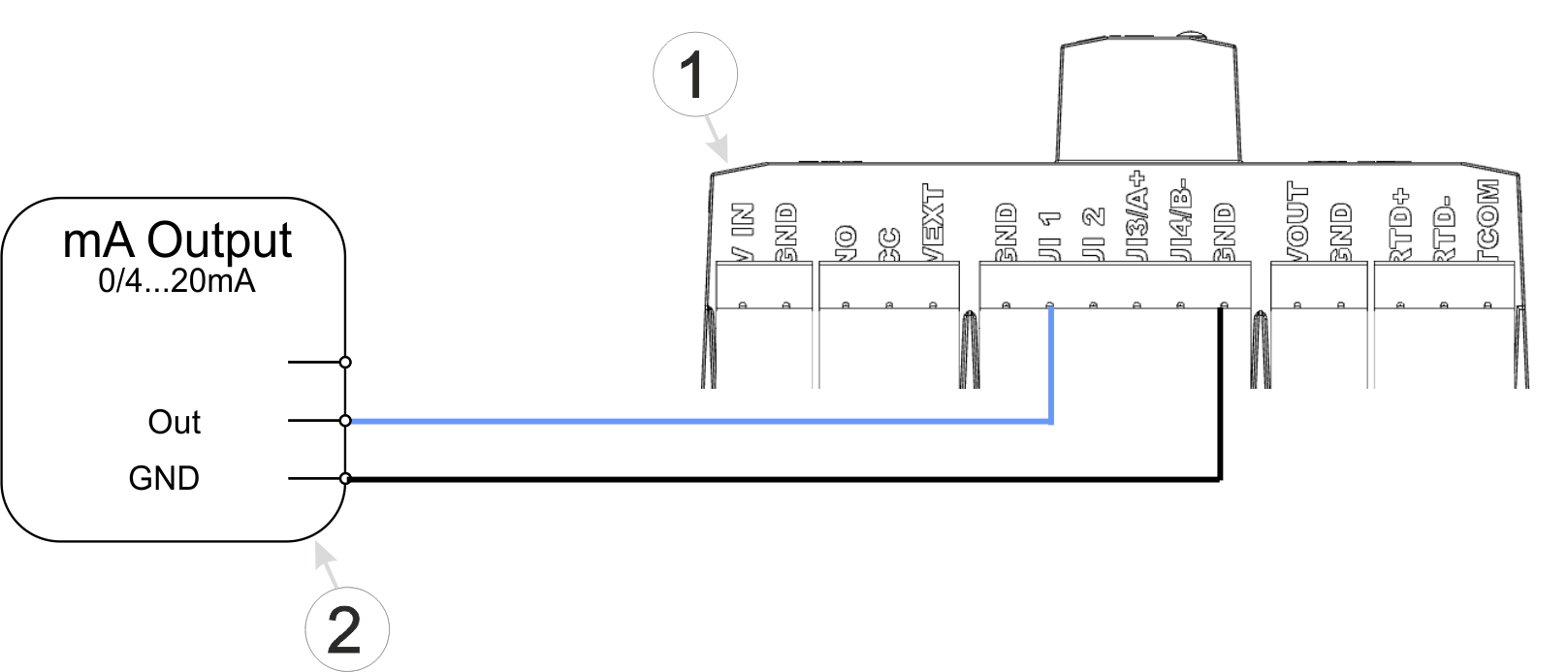
Connection examples (active mA output)
| 1 | Main terminal block of the 4-Channel Data Logger MBM | 2 | Active mA output, transducer or isolation transformer |
A detailed explanation is provided in section Connecting the sensors, actuators and power supply.
Activate transport mode by setting the "operating mode" in the "Basic settings" configuration section (see Basic settings) to "transport". After that, initiate a connection (see Aloha transmission mode) to transmit the changed configuration to the 4-Channel Data Logger MBM .
A detailed explanation is provided in section Storage of the product.


