External power supply unit "Power supply housing "
If an existing 230VAC supply circuit should be used to supply an additional device (e.g. the heating of a rain sensor) besides the 4-Channel Data Logger with DC voltage, the "Power supply housing "(301442) can be used. It has two separately secured 24VDC voltage outputs (T2A 250V for transmission devices, T10A 250V for e.g. heating).

Connecting the Power supply housing to the 4-Channel Data Logger
| 1 | Housing for outdoor installation 300x200x150mm (optional) | 4 | 230VAC supply lines |
| 2 | 4-Channel Data Logger | 5 | 24VDC line to supply the 4-Channel Data Logger |
| 3 | Power supply housing |
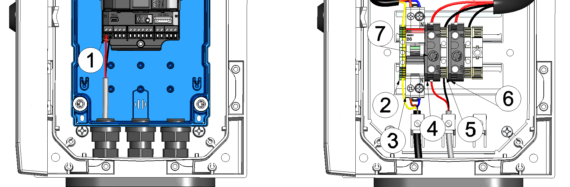
Connecting the Power supply housing to the 4-Channel Data Logger (detailed view)
| 1 | Connection for the external supply or charging voltage of the 4-Channel Data Logger | 5 | Ground connection |
| 2 | Earthing connection | 6 | 24VDC voltage output for heating |
| 3 | Circuit breaker | 7 | Fuse recess |
| 4 | 24VDC voltage output for transmission device |
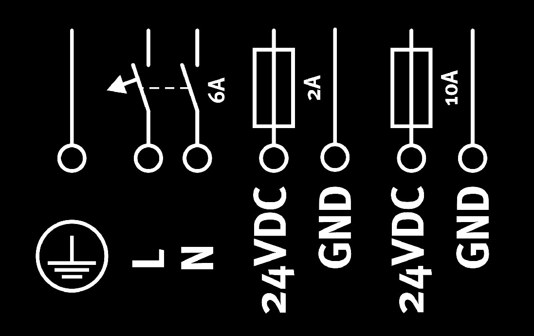
Connection diagram

|
230VAC input voltage | Protective conductor |
| L | Phase | |
| N | Neutral conductor | |
| 24VDC | Transmission device | 24VDC voltage output (T2A 250V fuse) |
| GND | Ground | |
| 24VDC | Heating | 24VDC voltage output (T10A 250V fuse) |
| GND | Ground |
- Set the switch of the circuit breaker to the position "off".
- Connect the 230VAC supply line to the terminals "L" and "N" of the circuit breaker
(rated current 6A ).
 Attention: All wiring work must be performed in the de-energised state.
 - Complete all steps from chapter Connecting the sensors, actuators and power supply.
Important: All safety instructions in chapter Connecting the sensors, actuators and power supply also apply when using the "Power supply housing ".
When reaching the step to connect the external supply or charging voltage, connect the 24VDC voltage output of the Power supply housing intended for the transmission device to the terminals "V IN" and "GND" of the main terminal block of the 4-Channel Data Logger .
For steps in which the supply or charging voltage should be switched on, the switch of the circuit breaker needs to be set to the position "on".


