Earthing of sensor cables
If the shield of a sensor cable requires earthing or needs to be included in the earthing concept of the facility, the Electrical bonding and cable support for myDatalogEASY IoT can be used. This extension set installed in the clamping space includes 3 shield connection terminals and adds an external earthing connection for the connection with the earth potential of the facility to the 4-Channel Data Logger .
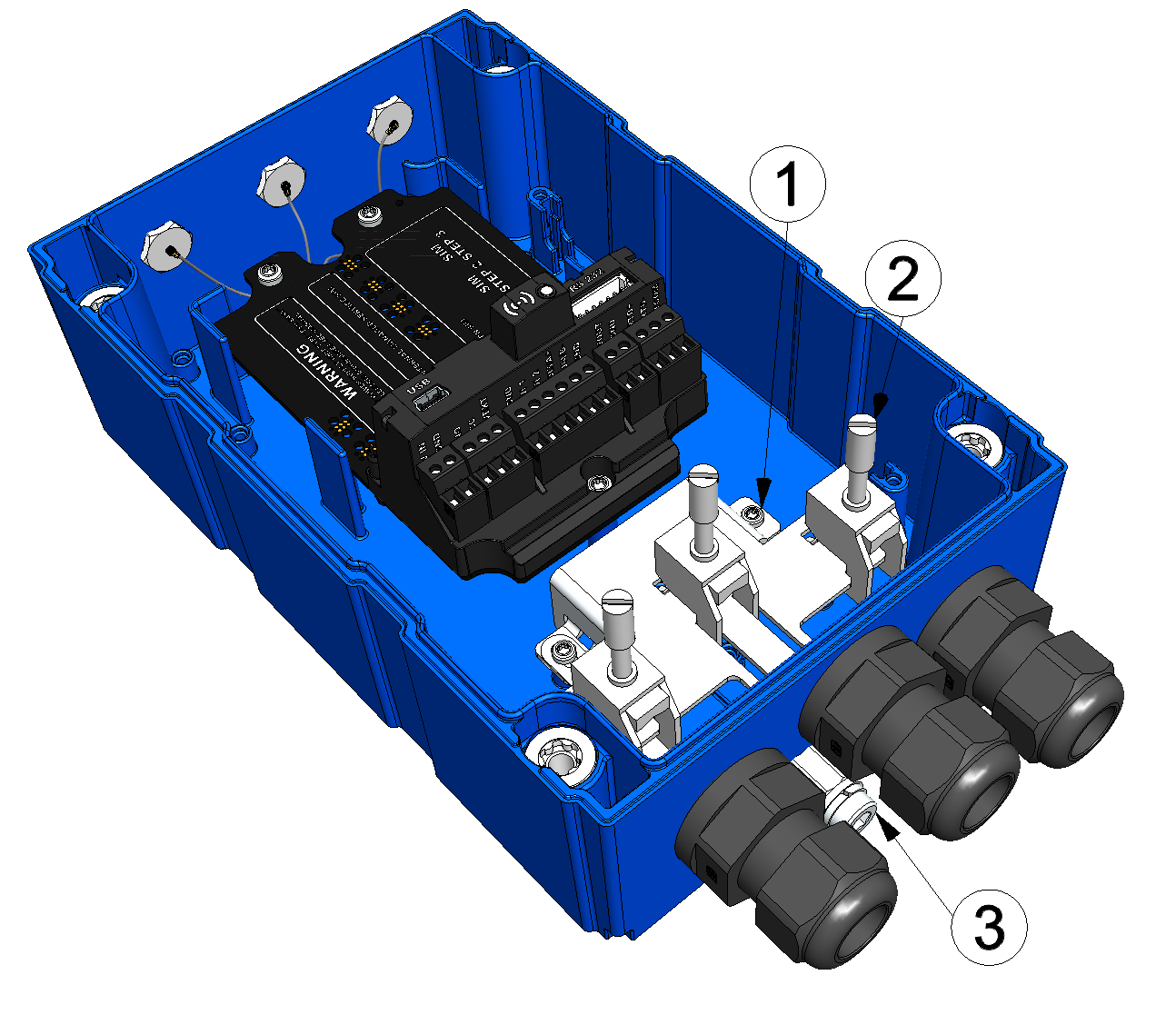
Earthing of sensor cables (view without power supply unit)
| 1 | Electrical bonding and cable support (301403) | 3 | Earth connection (minimum requirement for the earth cable: 4 mm²) |
| 2 | Shield connection terminal (cable diameter 3-8mm) |
- Connect the earth connection of the 4-Channel Data Logger to the earth potential of the facility. If the power supply unit is already inserted in the device, remove it from the 4-Channel Data Logger beforehand (see Replacing the power supply unit) .
- Remove the outer cable coating of all cables (sensor cable and/or supply of the 4-Channel Data Logger ) of which the shield should be earthed to lay bare the braid. The cable coating should be removed for a length of approx. 2,5 cm.
- Complete all steps from chapter Connecting the sensors, actuators and power supply.
Important: All safety instructions in chapter Connecting the sensors, actuators and power supply also apply when using the "Electrical bonding and cable support ".
Before the step for tightening the cable glands, complete the following steps.
- Thread the shield connection terminals into the base plate connected to the earth
connection as shown in the following figure. The small barbs of the shield connection
terminals must snap into the rectangular opening.

How-To-Video: Inserting the shield connection terminals 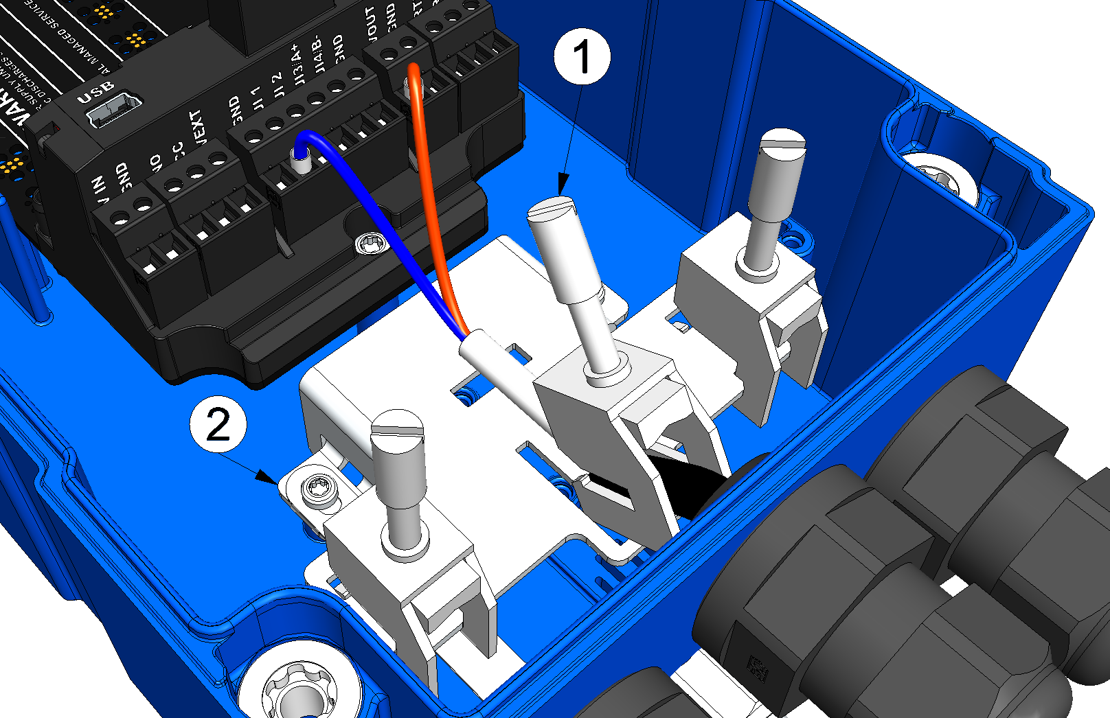
Inserting the shield connection terminals
1 Shield connection terminal (cable diameter 3-8mm) 2 Base plate connected to the earth connection - Set the sensor cable by fastenig the shield connection terminal.
Note: Ensure that the cable coating is not jammed between the base plate and the shield connection terminal, since correct earthing cannot be guaranteed in this case. In the case of sensor cables with an integrated pressure compensation tube, it is important to ensure that this is not pinched off. If the contact pressure is too low, however, correct earthing cannot be guaranteed.
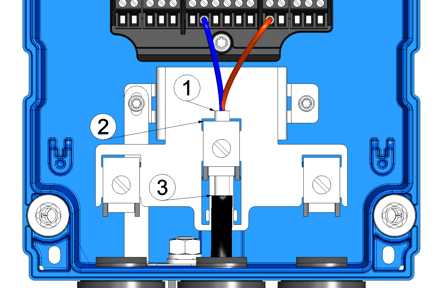
Fastenig the shield connection terminals
1 Braid (lay bare on a length of approx. 2,5cm) 3 Cable coating 2 Shield connection terminal (cable diameter 3-8mm)


