Online help for 4-Channel Data Logger
General product information
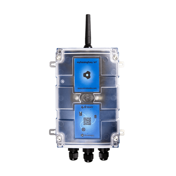
The 4-Channel
Data Logger is a data logger designed for stand-alone operation.
Product characteristics:
- Universal inputs for digital and analogue signals
- Switchable and adjustable supply voltage for sensors
- Isolated switch contact
- Internal battery compartment
- Battery, rechargeable battery or direct power supply
- Exactstate of charge of the battery using Coulombmethod
- Space for additional components in the housing
- Integrated charge control
- Configurable via web interface
- Device time synchronised with the sever
- Hardware real-time clock
- Very low commissioning & operating costs
- Integrated durable SIM chip
Application:
- Level measurement
- Flow measurement
- Temperature measurement
- Transmission of measurement values of probes
- Remote meter reading
This online help is applicable from:
Frequently asked questions (FAQs)
| Blink code | Colour | Description |
|---|---|---|
| 0x | --- | Transport lock (transmission OFF, measurement OFF) |
| 1x | green | Last connection OK |
| 2x | red | Last transmission faulty |
| 7x | red | Network block/no matching provider |
| 8x | red | No mobile network |
| 9x | red | incorrect PIN/1 attempt remaining |
| 10x | red | No mobile network connection |
| 11x | red | No server available |
| 12x | red | Faulty SIM chip |
A detailed explanation is provided in section Three colour status LED.
Yes.
The combi antenna "Flat antenna Disc multi band 2xFME-F 2m " (301196), which contains two mobile network antennas, is recommended in such cases. Alternatively, 2 separate antennas of the same type can also be used.
A list of available antennas is provided in section Antennas.
|
| How-To-Video: Triggering Aloha transmission mode |
Tap theMDN Magnet (206.803) for at least 3 sec. on the position shown in the following figure.
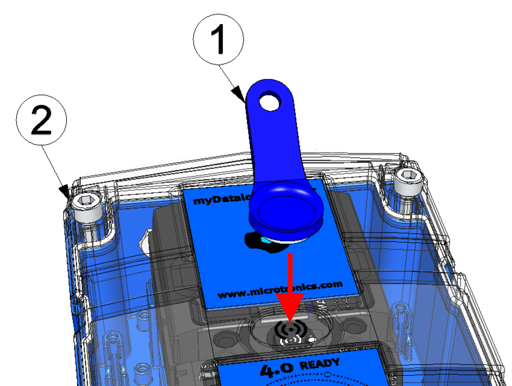
| 1 | MDN Magnet (206.803) | 2 | 4-Channel Data Logger |
Briefly (approx. 1 sec.) tap theMDN Magnet (206.803) on the position shown in the following figure.
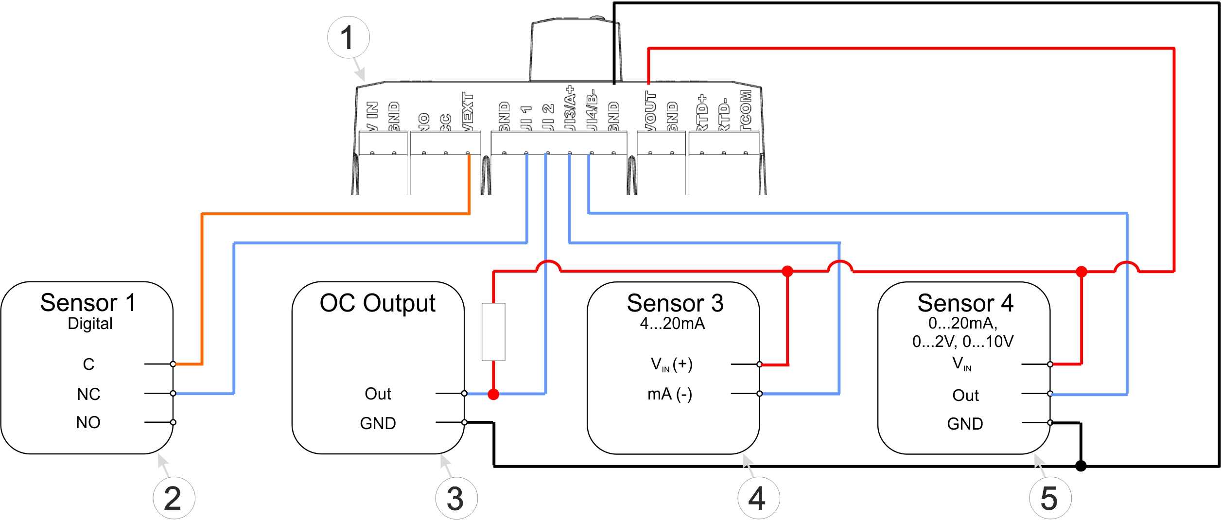
Connection examples (digital, open collector output, 0/4...20 mA, 0...2/10 V)
| 1 | Main terminal block of the 4-Channel Data Logger | 4 | 2-wire mA sensor |
| 2 | Isolated relay contact | 5 | 3-wire mA sensor or 3-wire U-sensor |
| 3 | Sensor with open collector output |
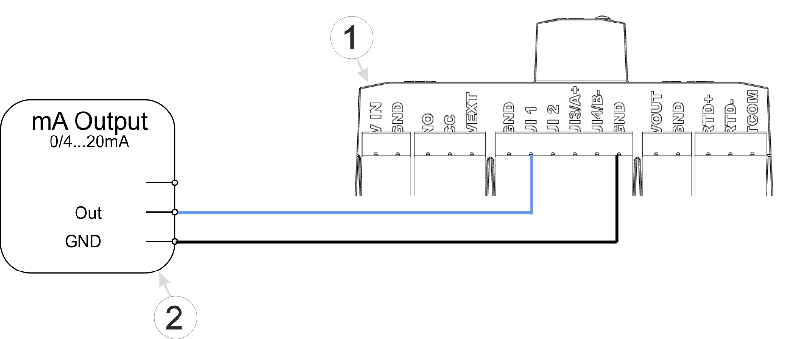
Connection examples (active mA output)
| 1 | Main terminal block of the 4-Channel Data Logger | 2 | Active mA output, transducer or isolation transformer |
A detailed explanation is provided in section Connecting the sensors, actuators and power supply.
Activate transport mode by setting the "operating mode" in the "Basic settings" configuration section (see Basic settings) to "transport". After that, initiate a connection (see Aloha transmission mode) to transmit the changed configuration to the 4-Channel Data Logger .
A detailed explanation is provided in section Storage of the product.


